Device for cutting substrate

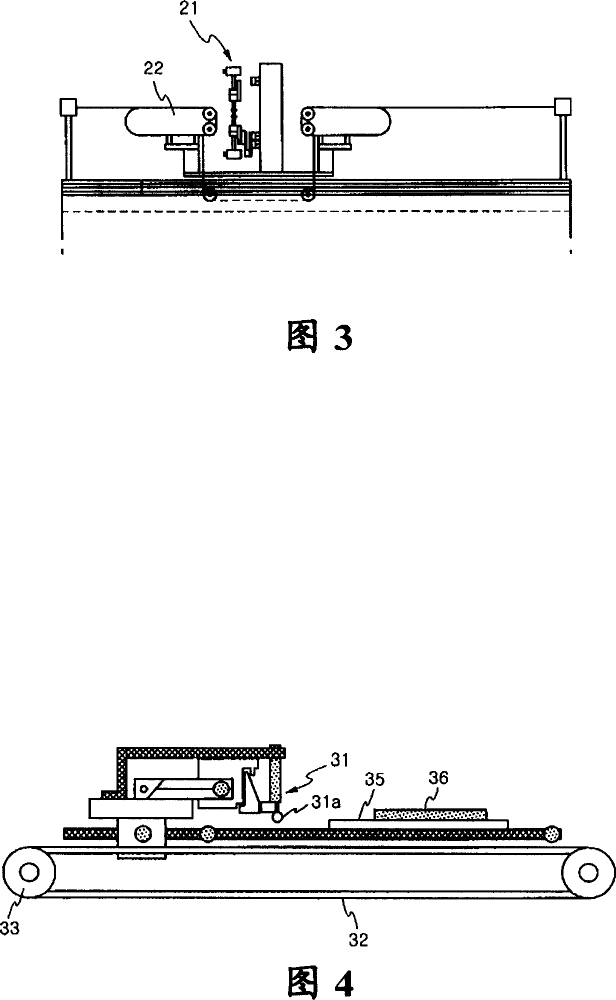
A technology for a reference positioning device and a substrate, which is applied to glass cutting devices, stone processing equipment, instruments, etc., can solve problems such as difficulty in controlling the precise position of the scriber 31 and increasing control errors of the conveyor belt 32.

Inactive Publication Date: 2007-04-25
TOP ENG CO LTD
View PDF0 Cites 17 Cited by
  • Summary
  • Abstract
  • Description
  • Claims
  • Application Information

AI Technical Summary

Problems solved by technology

Therefore, when the driving distance is enlarged, the control error of the conveyor b...

Method used


Image

  • Device for cutting substrate
  • Device for cutting substrate
  • Device for cutting substrate

Examples


Embodiment Construction

[0031] The present invention will now be described more fully hereinafter with reference to the accompanying drawings, in which preferred embodiments of the invention are shown. The invention may, however, encompass different forms and should not be construed as limited to the specific embodiments set forth herein. Rather, these specific embodiments are provided as examples to teach the invention. The same reference numerals denote the same elements.

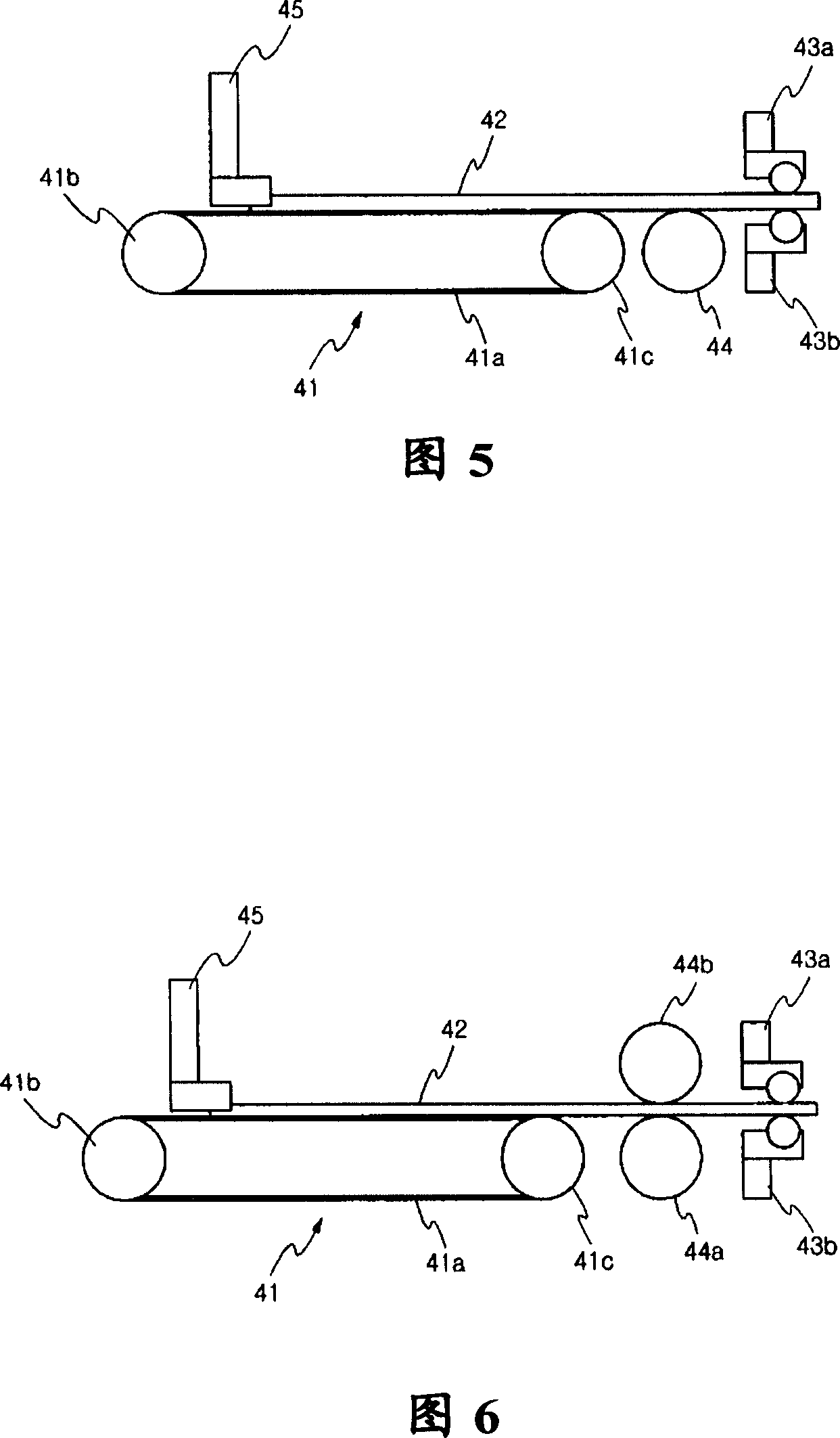
[0032] 5 is a view illustrating the structure of an apparatus for cutting a substrate according to an embodiment of the present invention, and FIG. 6 is a view illustrating the structure of another apparatus for cutting a substrate according to another embodiment of the present invention.

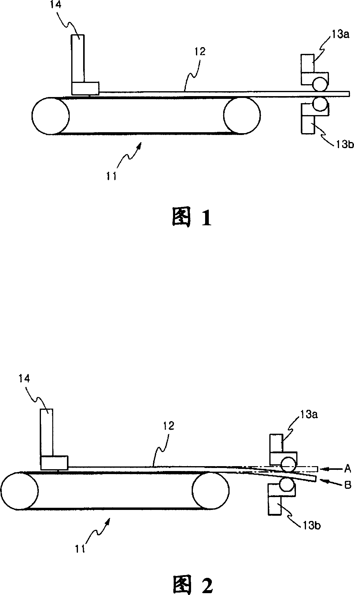
[0033] As shown in FIG. 5, the apparatus for cutting a substrate is used to cut a brittle substrate 42, such as a glass substrate. The scribing process uses a first scriber 43a and a second scriber 43b using cutting wheels.

[0034] The co...


PUM


Abstract

Disclosed is a device for cutting a substrate, wherein the brittle substrates are transported by the conveyer belt. The device comprises: a scriber for the lineation operation on the substrate; a conveyer belt for conveying the substrate to the scriber; and a reference locating device for supporting one end of the scriber on a prescribed reference position which is located between the scriber and the conveyer belt. Therefore, when using device, the cutting precision, the processing quality are enhanced and the cutting consistency is stably maintained.

Description

[0001] Cross References to Related Applications [0002] This application claims priority from Korean Patent Application No. 10-2005-0133560 filed on December 29, 2005, the entire contents of which are hereby incorporated by reference. technical field [0003] The present invention relates to an apparatus for cutting a substrate, and more particularly, to an apparatus for cutting a substrate in which a brittle substrate is conveyed by a conveyor belt. Background technique [0004] Generally, glass substrates are used for liquid crystal displays (LCDs) or organic light emitting devices (OLEDs), which are used as flat panel displays. [0005] When a glass substrate is used for the above device, it needs to be cut to fit the device. Devices with the function of cutting glass substrates are generally called scribers. [0006] A scriber performs a scribing process at a predetermined position of the glass substrate to be cut, and a breaker performs a cutting process along a slit...

Claims


Application Information

Patent Timeline
IPC IPC(8): G02F1/1333C03B33/02C03B33/00
CPCG02F1/1303B28D1/22B28D1/327H01L21/67092H10K71/00
Inventor 金埈煐
Owner TOP ENG CO LTD
Why Eureka
Try Eureka