Tool and method for scribing longitudinal lines on a cylindrical rod

a cylindrical rod and longitudinal line technology, applied in the direction of circular curve drawing instruments, writing aids, printing, etc., can solve the problems of undesirable time spent determining the angular position of the rod during surgery, problems for patients, and inability to accurately position the rod

Inactive Publication Date: 2006-03-30
ELECTROLIZING CORP
View PDF22 Cites 15 Cited by
  • Summary
  • Abstract
  • Description
  • Claims
  • Application Information

AI Technical Summary

Benefits of technology

[0007] A preferred version of the tool has a frame including a bed, with a groove in the bed. A clamp is mounted on the bed for clamping the rod in the predetermined position. Additional features allow for precise angular positioning of the rod and for scribing a dashed line on the rod.

Problems solved by technology

Because the surface finish of these rods is uniform and without markings, surgeons sometimes in the past have had problems in determining the angular orientation of the rod during the implanting procedure.
Time spent determining the angular position of the rod during the surgery is undesirable.
This extra time causes problems for the patient who must be in surgery for a longer time, and less importantly, reduces the surgeon's productivity.
However, a suitable means to apply these markings has not been available.

Method used


Image

  • Tool and method for scribing longitudinal lines on a cylindrical rod
  • Tool and method for scribing longitudinal lines on a cylindrical rod
  • Tool and method for scribing longitudinal lines on a cylindrical rod

Examples


Embodiment Construction

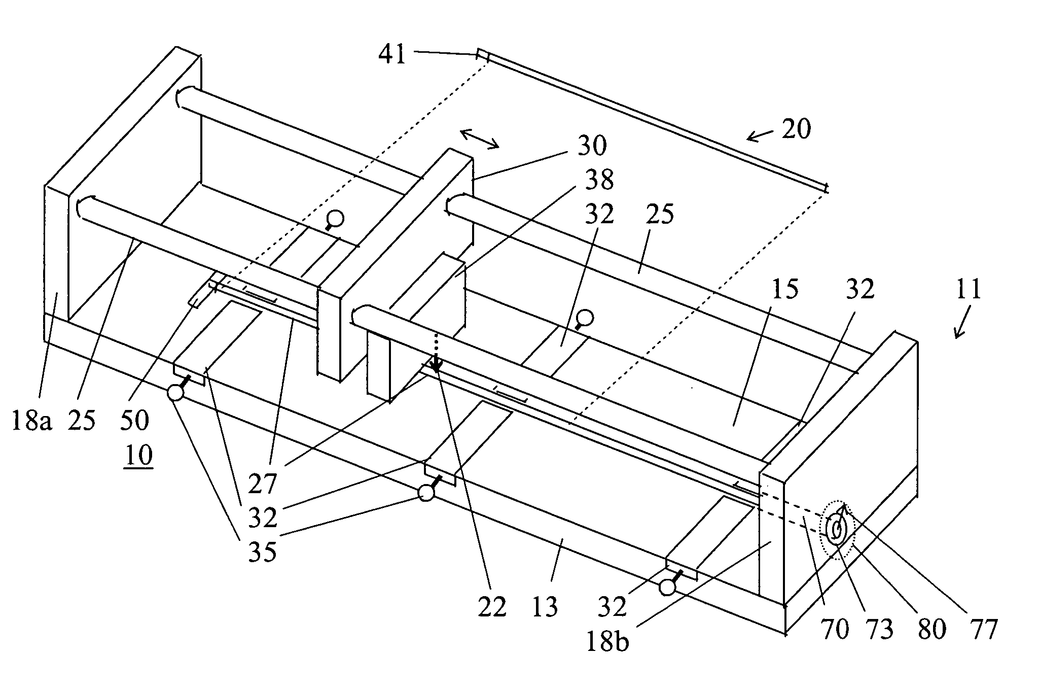
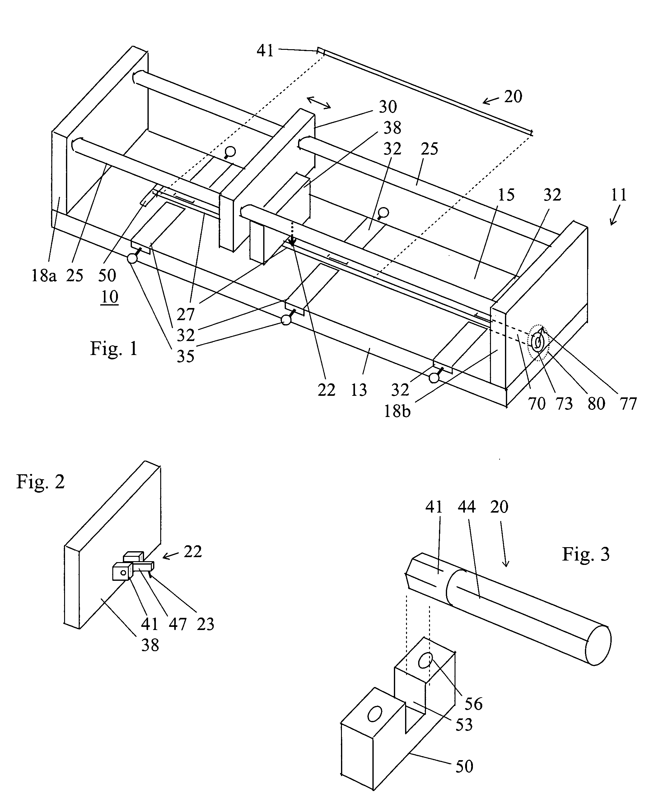
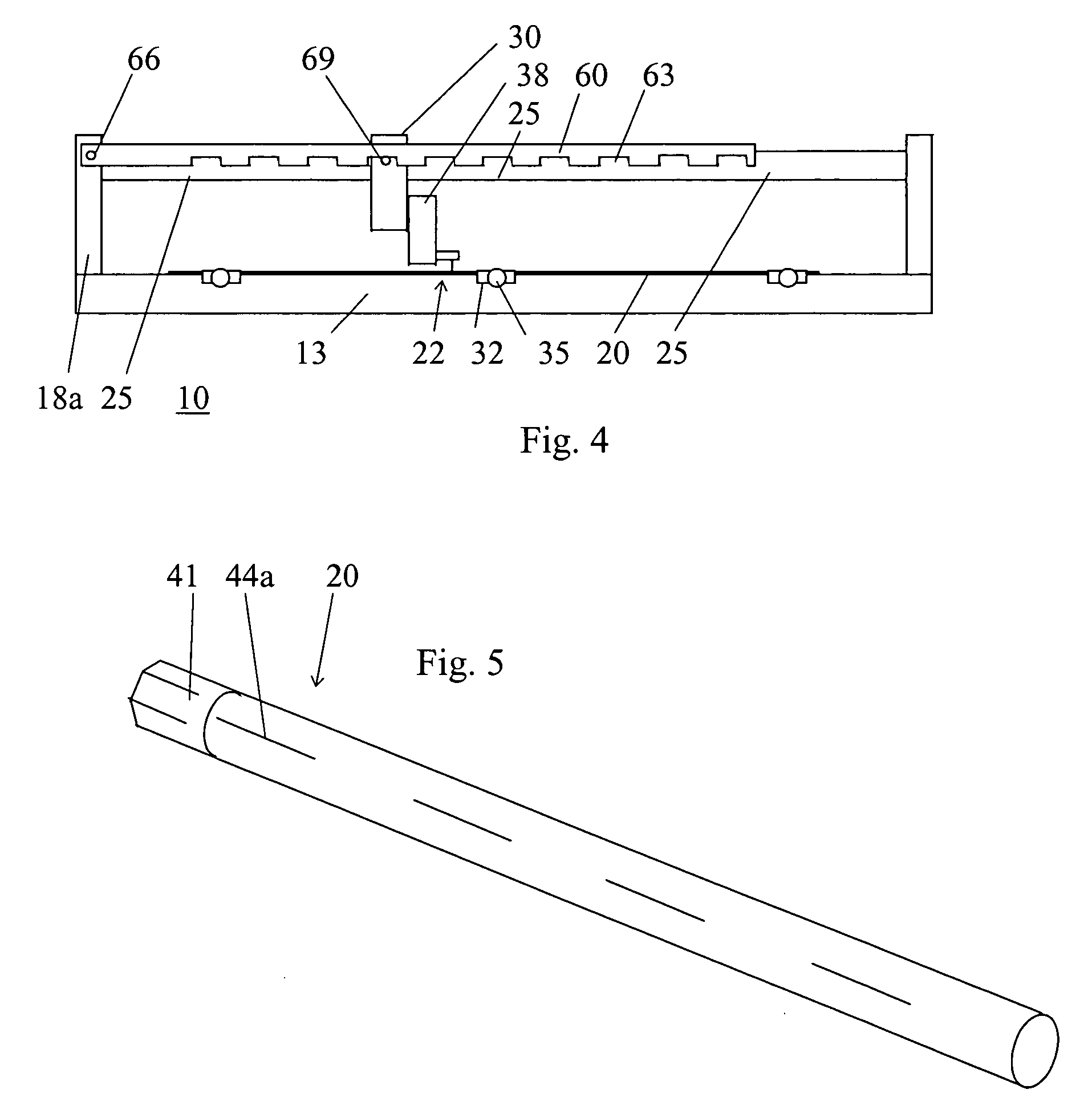
[0014]FIG. 1 shows a scribing tool 10 for scribing or marking a linear scratch or groove 44 along the length of a prosthetic rod 20 as shown in FIG. 4. Tool 10 comprises a frame 11 including an elongate bed 13 made of rigid material such as aluminum. Bed 13 has a flat surface 15 with a linear groove 27 machined therein extending along a substantial portion of the length of bed 13. Bed 13 may be in the range of 2-3 ft. long and 6-12 in. wide, depending on the maximum length of rod 20 to be scribed.

[0015] Frame 11 further includes a pair of track supports 18a and 18b made for example from aluminum and mounted on the ends of bed 13 to project at substantially right angles from flat surface 15 of bed 13. A pair of constant outer diameter round steel tubes or bars 25 are mounted between supports 18a and 18b to extend parallel to each other and form a guide track. The guide track can have other designs as well. One potential option is the traveler track units such as used in sailboats fo...


PUM


Abstract

A tool for scribing a longitudinal groove on an elongate cylindrical rod suitable for implanting as a prosthetic in a living being supports the rod in a linear groove on a bed of a frame of the tool. A track is mounted on the frame and runs parallel to the groove. A carrier mounted on the track can slide on the track in constant spaced relation to and along the groove. A scribe mounted on the carrier extends toward the groove to contact a rod in the predetermined position. A preferred version of the tool has a clamp mounted on the bed for clamping the rod in the predetermined position. Additional features allow for precise angular positioning of the rod and for scribing a dashed line on the rod. In use, the tool operator places the rod in the predetermined position in the groove. The scribe is then pressed into contact with the rod. While the scribe is in pressed contact with the rod, the operator slides the carrier along the track.

Description

BACKGROUND OF THE INVENTION [0001] Metal rods are used as orthopedic prostheses in a variety of applications. One particular application involves rods used as spinal prostheses. In this application, the rod is surgically implanted adjacent to the patient's spine and attached to individual vertebrae with screws, wires, etc. Titanium and stainless steel are most often used as the materials from which these metal rods are made. [0002] When preparing to implant a prosthetic rod, the surgeon will frequently bend the rod to conform to the individual patient's physiological condition. After bending, it is important to be able to determine the angular orientation of the rod. Because the surface finish of these rods is uniform and without markings, surgeons sometimes in the past have had problems in determining the angular orientation of the rod during the implanting procedure. [0003] Time spent determining the angular position of the rod during the surgery is undesirable. This extra time ca...

Claims


Application Information

Patent Timeline
Patent Type & Authority Applications(United States)
IPC IPC(8): B43L9/00
CPCB44B3/063B44B3/04
Inventor MCKAY, DAVID B.BRUCK, DARRYL R.SCHWARZ, EDWARD L.
Owner ELECTROLIZING CORP
Why Eureka
Try Eureka