Variable capacity multi-cylinder rotary compressor and its running method

A rotary compressor, multi-cylinder technology, which is applied in the direction of pump combination, mechanical equipment, machine/engine, etc. for elastic fluid rotary piston type/swing piston type, can solve the problems of difficulty in improving refrigeration capacity and rising cost, etc. Achieve low cost, improve energy efficiency and reduce power consumption

Inactive Publication Date: 2007-05-02
LG ELECTRONICS (TIANJIN) APPLIANCES CO LTD
0 Cites 27 Cited by

AI-Extracted Technical Summary

Problems solved by technology

However, due to the high price of the frequency conversion motor itself, it will increase the cost, and according...

Abstract

A volume-variable multi-cylinder rotation compressor is composed of casing, driver unit, at least more than 3 compression units and connection unit. Its running mode features that the volume of compressor can be controlled by 4 classes even if a constant-speed motor is used.

Application Domain

Technology Topic

Image

  • Variable capacity multi-cylinder rotary compressor and its running method
  • Variable capacity multi-cylinder rotary compressor and its running method
  • Variable capacity multi-cylinder rotary compressor and its running method

Examples

  • Experimental program(1)

Example Embodiment

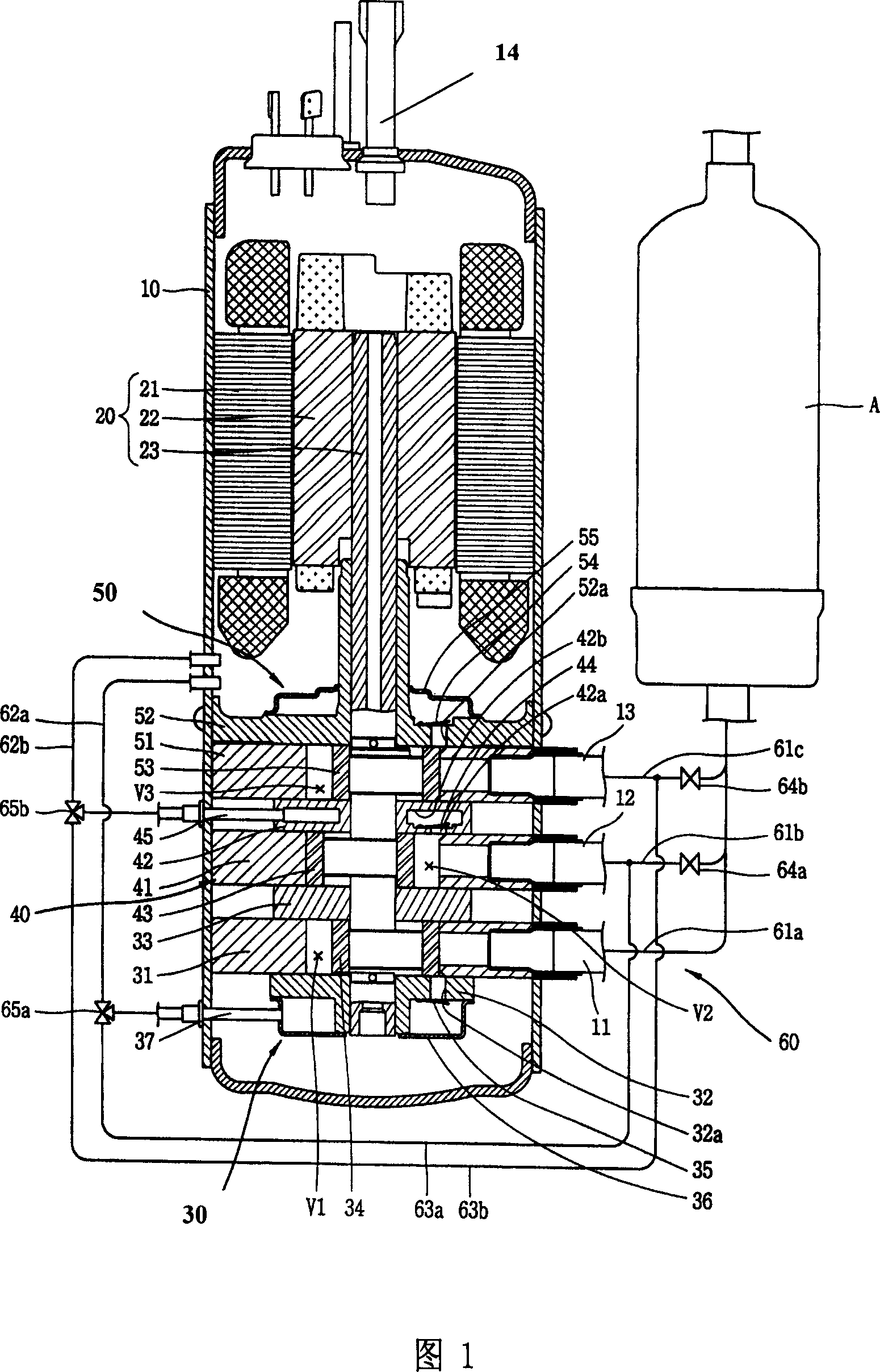
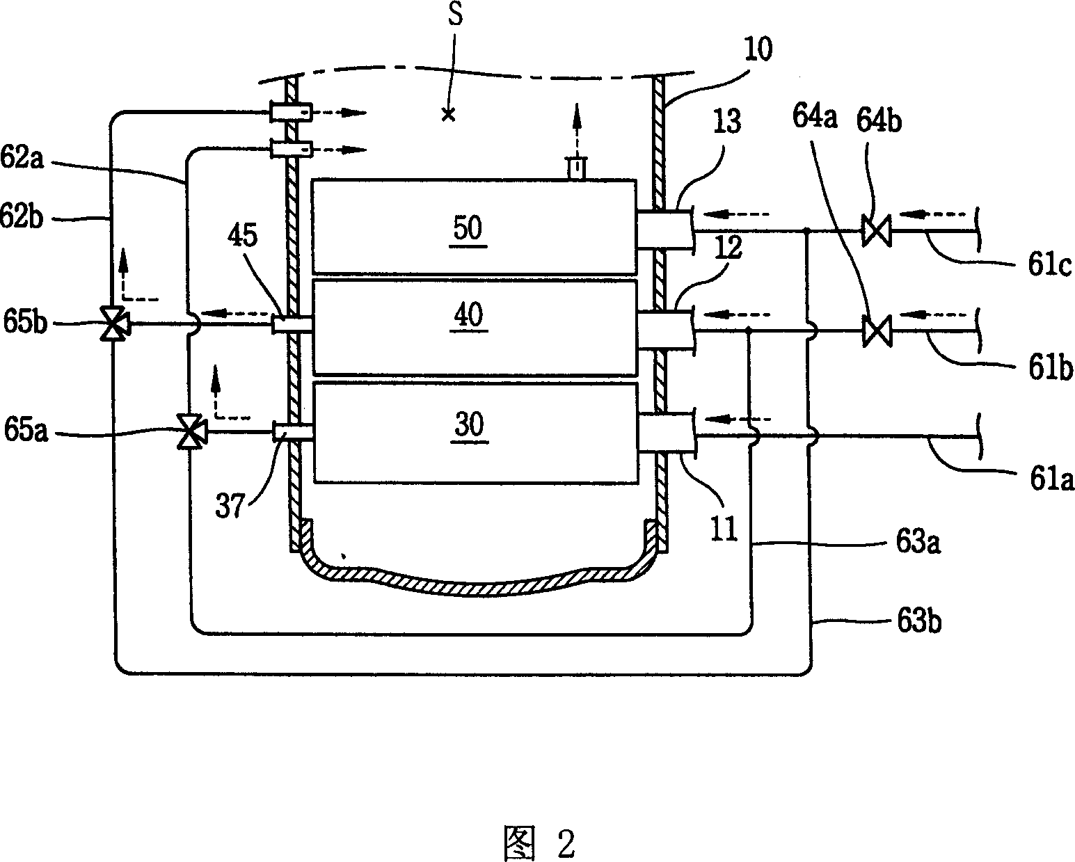
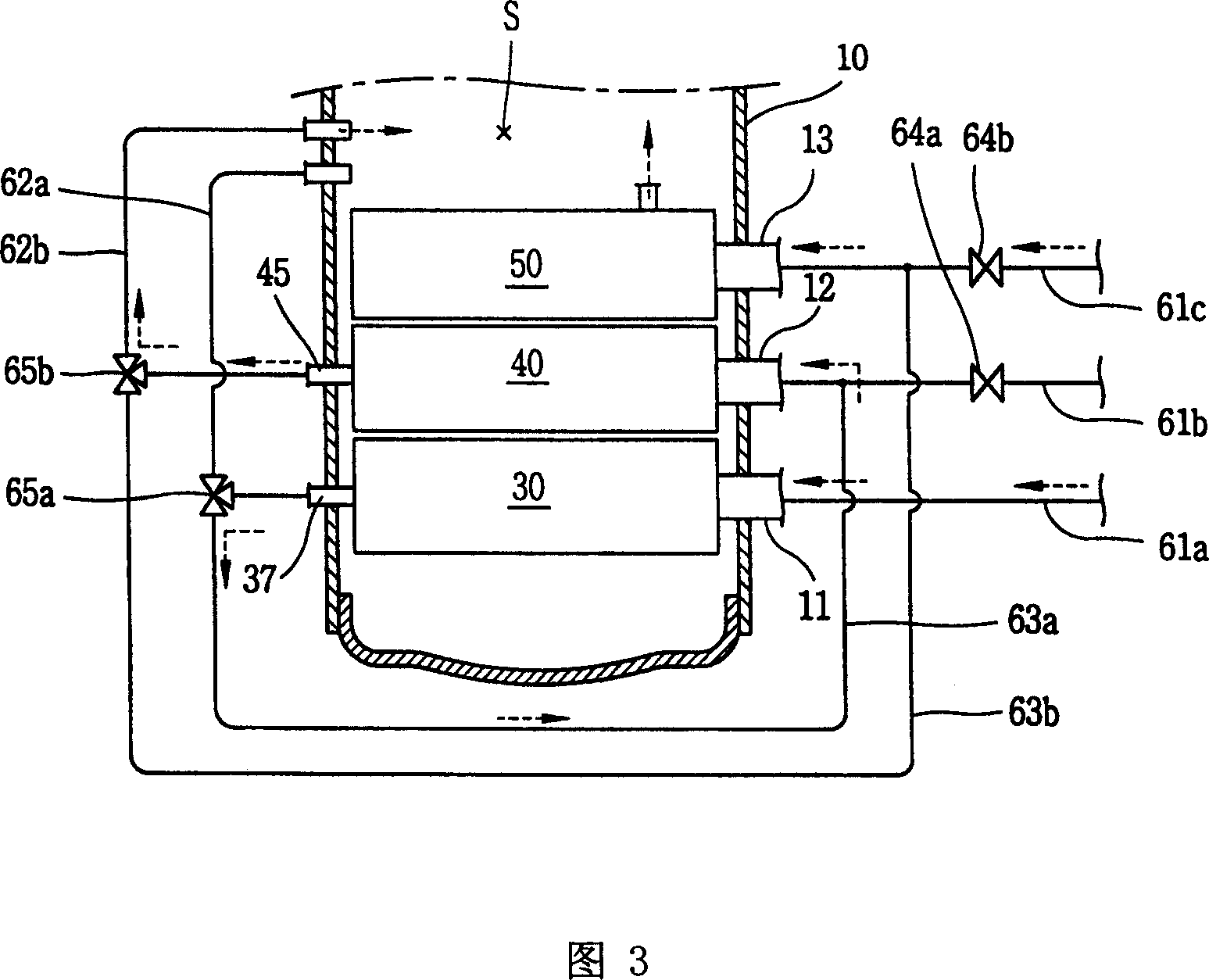
[0023]As shown in Figures 1 to 5, the variable capacity multi-cylinder rotary compressor provided by the present invention mainly includes a housing 10, a drive device 20, a first compression device 30, a second compression device 40, a third compression device 50, and Connecting device 60; a sealed space S is formed inside the housing 10; the driving device 20 is provided inside the housing 10, which can generate driving force; the first compression device 30, the second compression device 40, and the third compression device 50 are installed Inside the housing 10 and connected with the drive device 20 for compressing the refrigerant; the connecting device 60 is connected between the evaporator outlet in the refrigeration cycle system and the suction side of each compression device 30, 40, 50, and the phase The discharge side adjacent to each compression device communicates with the suction side of another compression device or the enclosed space S of the housing 10. The outlet of the evaporator in the refrigeration cycle system is communicated with the compression devices 30, 40, 50 through a plurality of refrigerant suction pipes 11, 12, 13 arranged on the housing 10, and the condenser inlet in the refrigeration cycle system is set through through The refrigerant discharge pipe 14 on the housing 10 communicates with the enclosed space S of the housing 10. The driving device 20 mainly includes a stator 21, a rotor 22 and a rotating shaft 23. The stator 21 is fixed inside the housing 10 and is connected to an external power source; the rotor 22 is installed inside the stator 21 with a certain gap between the stator 21 and can rotate under the interaction with the stator 21; the rotating shaft 23 and the rotor 22 is combined into one body, which can transmit driving force to the compression devices 30, 40, 50. Since the drive device 20 uses a constant speed motor, it is cheaper and more feasible than a variable frequency motor with a control driver, but a variable frequency motor can also be used according to the situation. The first compression device 30 mainly includes a first cylinder 31, a lower bearing 32, a first intermediate bearing 33, a first rolling ring 34, a first vane (not shown), a first discharge valve 35, and a lower muffler 36. The first cylinder 31 has an annular structure, which is installed inside the housing 10; the first intermediate bearing 33 and the lower bearing 32 respectively cover the upper and lower sides of the first cylinder 31, thereby forming the first inner space V1, and The rotating shaft 23 is supported in the radial and axial directions; the first rolling ring 34 is sleeved outside the lower eccentric portion of the rotating shaft 23, which can rotate in the first internal space V1 of the first cylinder 31 to compress the refrigerant; In contact with the outer circumferential surface of the first rolling ring 34, the first vane, not shown in the figure, is provided inside the first cylinder 31, which can move in the radial direction, so that the first internal space of the first cylinder 31 can be removed. V1 is divided into a first suction chamber and a first compression chamber; the first discharge valve 35 is fixed to the lower bearing 32, which is used to open and close the first discharge hole 32a communicating with the first compression chamber, thereby controlling the flow from the first compression chamber The discharged refrigerant; the lower muffler 36 is installed in the lower part of the lower bearing 32, and can cover the first discharge valve 35. In addition, one side of the lower muffler 36 is also provided with a first discharge guide pipe 37 that penetrates the housing 10 and is connected to a first discharge-side connecting pipe 62a and a first bypass-side connecting pipe 63a through a first switching valve 65a described later. . The second compression device 40 mainly includes a second cylinder 41, a second intermediate bearing 42, a second rolling ring 43, a second vane (not shown), and a second discharge valve 44. The second cylinder 41 has an annular structure, which is located on the upper side of the first cylinder 31 and is in contact with the first intermediate bearing 33; the second intermediate bearing 42 is fixed to the upper part of the second cylinder 41, thereby forming the second internal space V2. , While supporting the rotating shaft 23 in the axial direction; the second rolling ring 43 is sleeved outside the middle eccentric part of the rotating shaft 23, which can rotate in the second internal space V2 of the second cylinder 41, thereby compressing the refrigerant; The outer circumferential surface of the second rolling ring 43 is in contact with each other, and a second vane not shown in the figure is provided inside the second cylinder 41, which can move in the radial direction, so that the second internal space V2 of the second cylinder 41 can be moved. Divided into a second suction chamber and a second compression chamber; the second discharge valve 44 is fixed to one side of the second intermediate bearing 42, which is used to open and close the second discharge hole 42a communicating with the second compression chamber, thereby controlling the 2 The refrigerant discharged from the compression chamber. In addition, the inside of the second intermediate bearing 42 is also formed with a discharge flow path 42b in which the second discharge valve 44 can be mounted, and the outlet of the discharge flow path 42b is provided with a penetrating through the housing 10 and passing through a second switching valve 65b which will be described later. The second discharge guide pipe 45 to which the second discharge side connection pipe 62b and the second bypass side connection pipe 63b are connected. The third compression device 50 mainly includes a third cylinder 51, an upper bearing 52, a third rolling ring 53, a third vane (not shown), a third discharge valve 54 and an upper muffler 55. The third cylinder 51 has an annular structure, which is located on the upper side of the second cylinder 41 and is in contact with the second intermediate bearing 42; the upper bearing 52 is fixed to the upper part of the third cylinder 51, thereby forming the third internal space V3 together, and The rotating shaft 23 is supported in the radial direction; the third rolling ring 53 is sleeved outside the upper eccentric portion of the rotating shaft 23, and it can rotate in the third internal space V3 of the third cylinder 51, thereby compressing the refrigerant; The outer circumferential surfaces of the three rolling rings 53 are in contact with each other. The third vane, not shown in the figure, is provided inside the third cylinder 51, which can move in the radial direction, so that the third internal space V3 of the third cylinder 51 can be divided into The third suction chamber and the third compression chamber; the third discharge valve 54 is fixed on the side of the upper bearing 52, which is used to open and close the third discharge hole 52a communicating with the third compression chamber, thereby controlling the third compression chamber The discharged refrigerant; the upper muffler 55 is mounted on the upper part of the upper bearing 52, and can cover the third discharge valve 54. In addition, the volumes of the first cylinder 31, the second cylinder 41, and the third cylinder 51 are all different, but considering that the discharge side of the third cylinder 51 is located inside the housing 10, the volume of the third cylinder 51 is designed to be the smallest. The second cylinder 41 is centered, and the first cylinder 31 is designed to be the largest. The connecting device 60 mainly includes a first suction-side connecting pipe 61a, a second suction-side connecting pipe 61b, a third suction-side connecting pipe 61c, a first discharge-side connecting pipe 62a, a second discharge-side connecting pipe 62b, and a first on-off valve. 64a, the second on-off valve 64b, the first bypass-side connecting pipe 63a, the second bypass-side connecting pipe 63b, the first switching valve 65a, and the second switching valve 65b. The first suction-side connection pipe 61a, the second suction-side connection pipe 61b, and the third suction-side connection pipe 61c are formed by branching from the outlet side of the liquid tank A, and are connected to each other through the refrigerant suction pipes 11, 12, and 13 The suction side of each cylinder 31, 41, 51; the first discharge side connection pipe 62a communicates from the first discharge guide pipe 37 to the inside of the housing 10; the second discharge side connection pipe 62b communicates from the second discharge guide pipe 45 to the housing 10 The first bypass-side connecting pipe 63a is formed by branching from the first discharge guide pipe 37 and the first discharge-side connecting pipe 62a, and is connected to the second suction-side connecting pipe 61b; the second bypass-side connecting pipe 63b It is formed by branching from the second discharge guide pipe 45 and the second discharge side connecting pipe 62b, and is connected to the third suction side connecting pipe 61c; the first on-off valve 64a and the second on-off valve 64b are respectively installed in the second suction The side connecting pipe 61b and the third suction side connecting pipe 61c; and the first switching valve 65a and the second switching valve 65b are installed on the discharge guide pipes 37, 45, the discharge side connecting pipes 62a, 62b, and the bypass side connecting pipe, respectively The position of the connection point of 63a, 63b. In addition, the opening and closing valves 64a, 64b are both check valves, and compared with the positions where the bypass-side connecting pipes 63a, 63b are connected, they are preferably located on the refrigerant inflow side. The switching valves 65a and 65b are preferably three-way valves.
[0024] The following describes the operation of the variable capacity multi-cylinder rotary compressor provided by the present invention: When the stator 21 on the drive device 20 is powered on, the rotor 22 will rotate, thereby driving the rotating shaft 23 to rotate together, thereby turning The rotational force of the driving device 20 is transmitted to the first compression device 30, the second compression device 40, and the third compression device 50, and the opening and closing valves 64a, 64b and the switching valve 65a can be adjusted appropriately according to the capacity required by the air conditioner , 65b, so as to determine whether to operate in a powerful mode that can generate a large capacity of cooling power or an energy-saving mode that can generate a small capacity of cooling power. For example, as shown in FIG. 2, when operating in the power mode, both the first on-off valve 64a and the second on-off valve 64b must be opened. At this time, the refrigerant from the evaporator will flow into the first compression device 30 and the second compression device. The device 40 and the third compression device 50 compress the refrigerant in each of the compression devices 30, 40, and 50. At the same time, adjust the first switching valve 65a so that the first discharge guide pipe 37 communicates with the first discharge side connecting pipe 62a, and adjust the second switching valve 65b to connect the second discharge guide pipe 45 to the second discharge side. The pipe 62b is connected, so that the refrigerant discharged from each compression device 30, 40, 50 will be directly discharged to the enclosed space S of the casing 10, thereby generating 100% cooling power. On the contrary, as shown in FIG. 3, when operating in the energy-saving mode 1, the second on-off valve 64b is opened and the first on-off valve 64a is closed. At this time, the refrigerant from the evaporator will directly flow into the first compression device 30 and The third compression device 50. At the same time, adjust the first switching valve 65a so that the first discharge guide pipe 37 communicates with the first bypass-side connecting pipe 63a, and adjust the second switching valve 65b so that the second discharge guide pipe 45 and the second discharge side The connecting pipe 62b is connected, so that the refrigerant compressed for the first time in the first compression device 30 will flow into the second discharge guide pipe 37, the first bypass-side connecting pipe 63a, and the second suction-side connecting pipe 61b. The inside of the compression device 40 is compressed for the second time, and then discharged to the sealed space S of the housing 10 through the second discharge guide pipe 45 and the second discharge side connecting pipe 62b. At the same time, the refrigerant flowing into the third compression device 50 is compressed in its interior and is directly discharged into the enclosed space S of the housing 10. Therefore, only the interference between the first compression device 30 and the third compression device 50 occurs during the operation of the energy-saving mode 1 The cooling power corresponding to the volume. In addition, as shown in FIG. 4, when operating in the energy-saving mode 2, the first on-off valve 64a is opened and the second on-off valve 64b is closed. At this time, the refrigerant from the evaporator will directly flow into the first compression device 30 and The second compression device 40. At the same time, adjust the first switching valve 65a so that the first discharge guide pipe 37 communicates with the first discharge side connecting pipe 62a, and adjust the second switching valve 65b so that the second discharge guide pipe 45 and the second bypass side The connecting pipe 63b communicates with each other, so that the refrigerant flowing into the first compression device 30 is compressed in the inside thereof and then directly discharged to the sealed space S of the casing 10. At the same time, the refrigerant compressed for the first time in the second compression device 40 will flow into the third compression device 50 through the second discharge guide pipe 45, the second bypass-side connecting pipe 63b, and the third suction-side connecting pipe 61c. The inside of the compressor is compressed for the second time, and then is directly discharged to the enclosed space S of the housing 10, so only the cooling force corresponding to the volume of the first compression device 30 and the second compression device 40 is generated during the energy-saving mode 2 operation. In addition, as shown in FIG. 5, when operating in the energy-saving mode 3, both the first on-off valve 64a and the second on-off valve 64b are closed. At this time, the refrigerant from the evaporator will directly flow into the first compression device 30. At the same time, adjust the first switching valve 65a and the second switching valve 65b so that the first discharge guide pipe 37 and the second discharge guide pipe 45 are connected to the first bypass-side connecting pipe 63a and the second bypass-side connecting pipe 63b, respectively. In this way, the refrigerant flowing into the first compression device 30 will flow into the second compression device 40 after the first compression inside, and flow into the third compression device 50 after the second compression device 40 undergoes the second compression. The third compression is performed and the last is discharged to the enclosed space S of the casing 10. Therefore, only the cooling power corresponding to the volume of the first compression device 30 is generated during the operation in the energy-saving mode 3. For reference, the above-mentioned embodiment is described with three compression devices as an example, but a rotary compressor with four or more compression devices can also adopt this method.

PUM

no PUM

Description & Claims & Application Information

We can also present the details of the Description, Claims and Application information to help users get a comprehensive understanding of the technical details of the patent, such as background art, summary of invention, brief description of drawings, description of embodiments, and other original content. On the other hand, users can also determine the specific scope of protection of the technology through the list of claims; as well as understand the changes in the life cycle of the technology with the presentation of the patent timeline. Login to view more.

Similar technology patents

Thin walled, two component cartridge casing

InactiveUS20070214992A1Eliminate operationLow costCartridge ammunitionCarbon steelThin walled
Owner:TECH CORPORATION CO LTD

Classification and recommendation of technical efficacy words

  • Low cost
  • Versatile

Semiconductor device

InactiveUS6975142B2Low costReduce manufacturing stepsTransistorSolid-state devicesVoltage amplitudeSemiconductor
Owner:SEMICON ENERGY LAB CO LTD
Why Eureka
Try Eureka