Conduction system applicable to plating equipment

A technology of electroplating equipment and conductive heads, which is applied in the field of conductive systems, can solve the problems of small application range, easy winding, production danger, etc., and achieve the effects of guaranteed electroplating effect, convenient connection and simple structure

Inactive Publication Date: 2007-05-09
DONGGUAN CHAULEONG TELECOM TECH CO LTD
View PDF0 Cites 7 Cited by
  • Summary
  • Abstract
  • Description
  • Claims
  • Application Information

AI Technical Summary

Problems solved by technology

[0002] Today's electroplating process requires that the workpiece to be plated must be electrically charged during the electroplating process. There are currently two main ways to energize the workpiece, but both belong to the fixed point conduction method. One is that the static workpiece conducts electricity, that is, the processed The workpiece is placed statically in the electroplating pool, and the electroplating solution or the workpiece itself can be electrified to ensure the success of electroplating. However, this technology is increasingly unsuitable for the requirements of electroplating accuracy. In occasions with high requirements, the above-mentioned processing methods obviously cannot meet the requirements due to the gravity of the workpiece itself and the electroplating solution; the second is that for a regular geometric body with regular motion, the workpiece can be continuously energized at a fixed point, and the workpiece can be transferred to a certain Do simple gyrating motion or rocking motion in a specific direction, that is, electrify

Method used


Image

  • Conduction system applicable to plating equipment
  • Conduction system applicable to plating equipment

Examples


Embodiment Construction

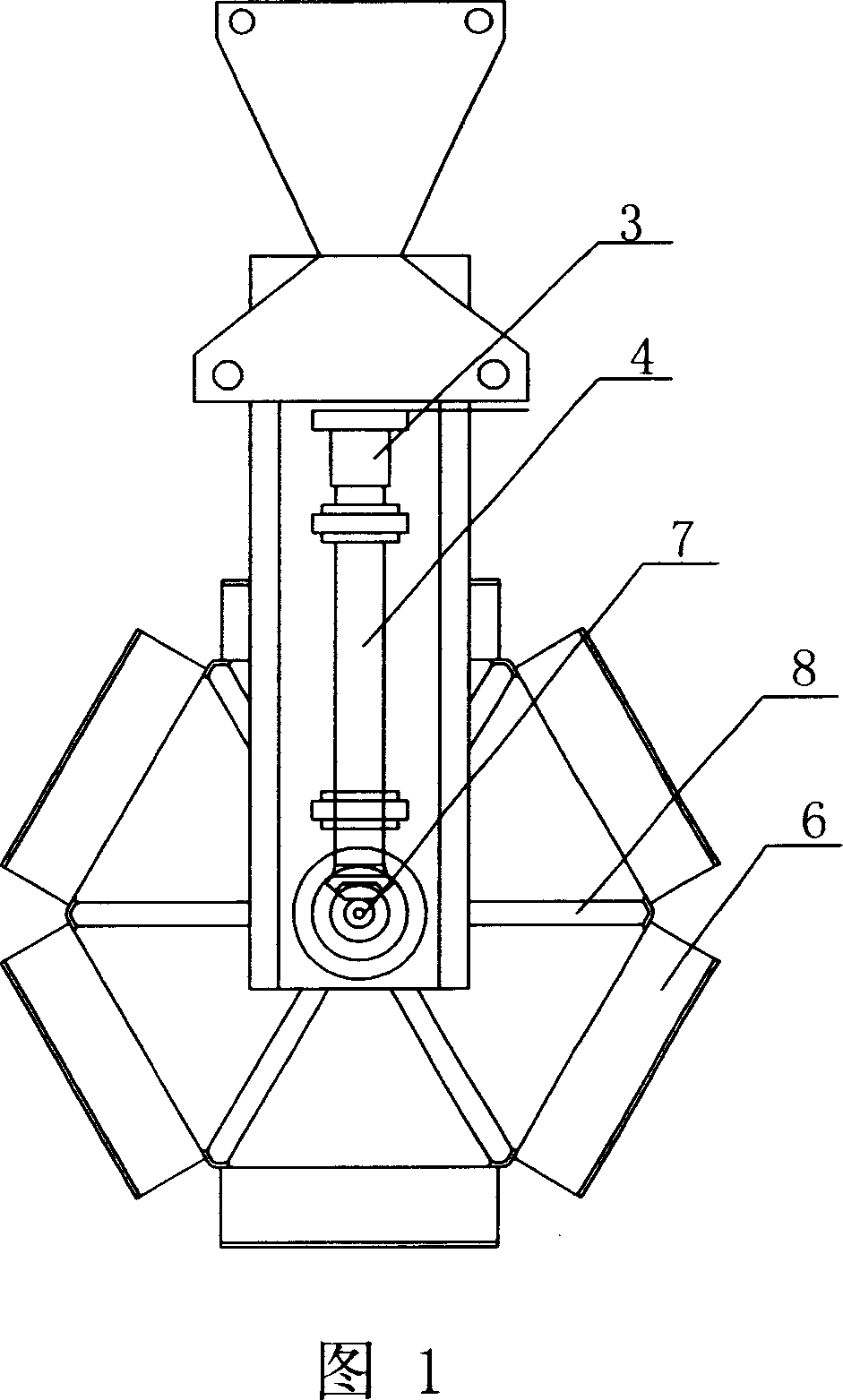
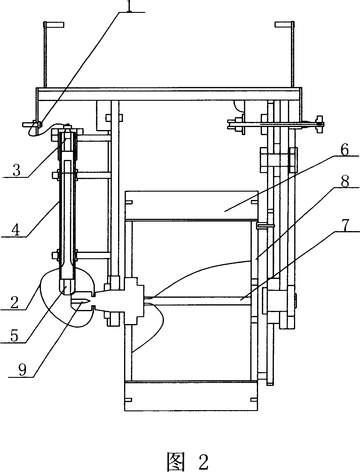
[0009] Below in conjunction with accompanying drawing, the present invention is further described: as shown in Figure 1, a kind of conductive system that is applied to electroplating equipment comprises copper conductive rod 1, flexible wire 2, mercury conductive device 3 and conductive head fixed sleeve 4 and steering cone Gear 5, the negative electrode of the power supply is connected to the cathode hook of the workpiece holder through them. The copper conductive rod 1 is connected to the power supply, and is connected with the transmission shaft 7 and the hexagonal iron frame 8 of the workpiece fixing frame 6 through the wire 2. In order to prevent the wire from being kinked when the workpiece fixing frame 6 rotates, the bottom of the conductive head fixing sleeve 4 is equipped with The bevel gear 9 that turns to the bevel gear 5 and the shaft end socket of the transmission shaft 7 of the hexagonal iron frame 8 forms a bevel gear transmission, and the conductive head fixing ...


PUM


Abstract

This invention relates to the conductive system of electroplating equipment. The system is composed of a copper conductive rod, conductive wires, and a conductive heat fixation cannula. The copper conductive rod is connected with the power supply. Besides, the copper conductive rod is also connected with the iron frame through the conductive heat fixation cannula via conductive wires, and through the power shaft of the roll frame, and is fixed on the wall. The conductive system can continuously supply electricity for work pieces during the electroplating, and does not limit the motion of work pieces. Besides, the conductive system is simple and convenient.

Description

technical field [0001] The invention relates to a conductive system, in particular to a conductive system mainly used in electroplating equipment. Background technique [0002] Today's electroplating process requires that the workpiece to be plated must be electrically charged during the electroplating process. There are currently two main ways to energize the workpiece, but both belong to the fixed point conduction method. One is that the static workpiece conducts electricity, that is, the processed The workpiece is placed statically in the electroplating pool, and the electroplating solution or the workpiece itself can be electrified to ensure the success of electroplating. However, this technology is increasingly unsuitable for the requirements of electroplating accuracy. In occasions with high requirements, the above-mentioned processing methods obviously cannot meet the requirements due to the gravity of the workpiece itself and the electroplating solution; the second i...

Claims


Application Information

Patent Timeline
IPC IPC(8): C25D17/00
Inventor 李月亮
Owner DONGGUAN CHAULEONG TELECOM TECH CO LTD
Why Eureka
Try Eureka