

Panel with moveable mechanism of indoor machine of air conditioner
An air-conditioning indoor unit and indoor unit technology, which are applied in air-conditioning systems, space heating and ventilation, household heating and other directions, can solve the problem that the accuracy of parts cannot be effectively controlled, the accuracy of moving mechanism parts is not enough, and the overall air conditioner is affected. effect and other issues, to achieve the effect of easy cleaning and maintenance, simple and controllable running track, and not easy to sound abnormal
- Summary
- Abstract
- Description
- Claims
- Application Information
AI Technical Summary
Problems solved by technology
Method used
Image

Examples
Embodiment 1
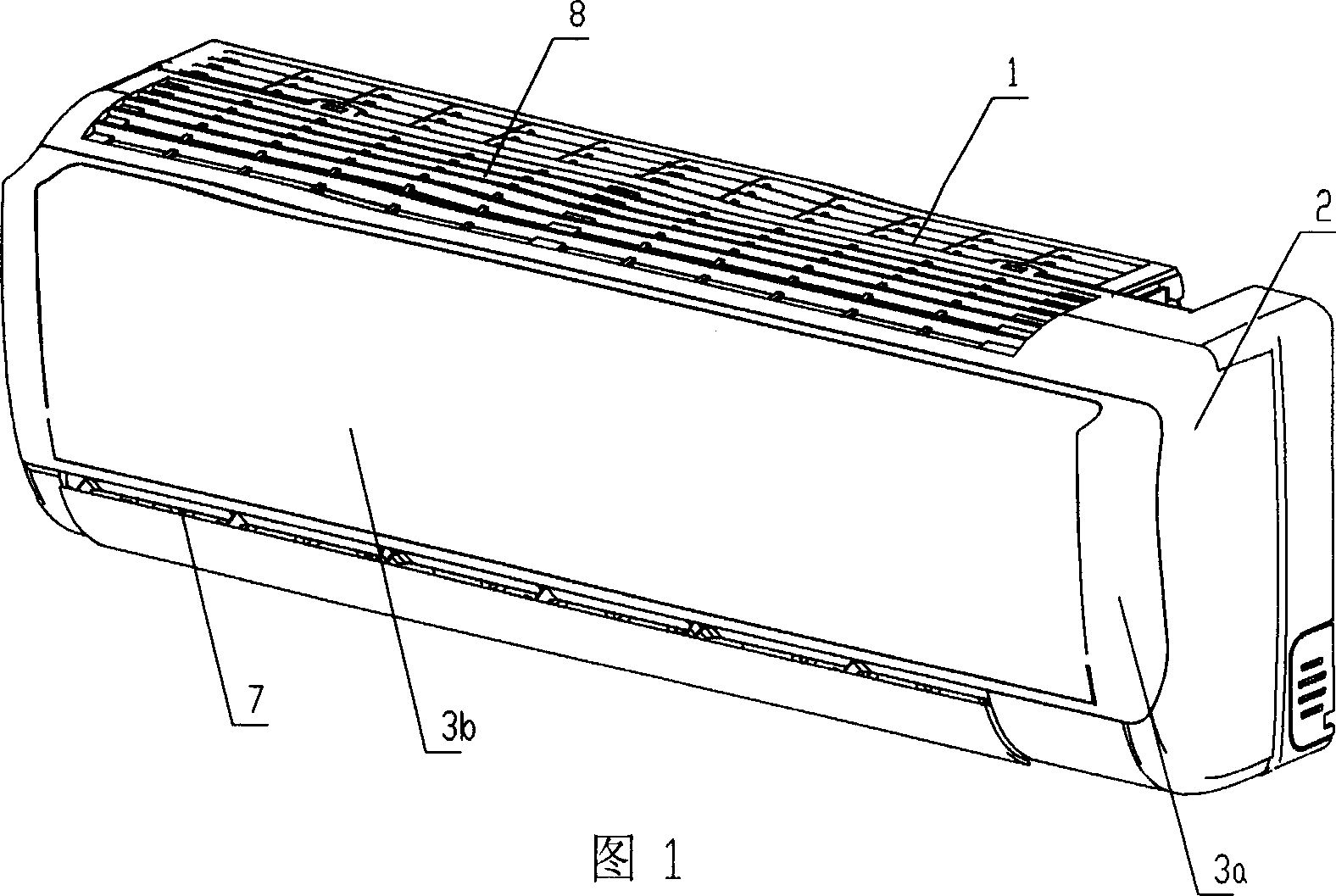
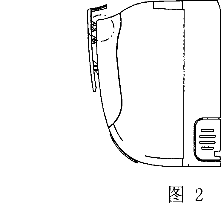
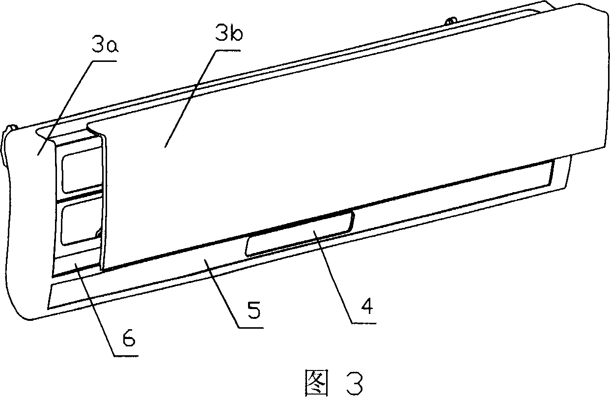
[0032] The panel of the present invention is installed on the indoor unit of the air conditioner, as shown in Figures 1, 2, 3, and 4, it includes a base 1, an outer cover 2, a fixed panel 3a, a movable panel 3b, a display part 4 and a decoration on the fixed panel 3a Bar 5, the outer cover 2 is installed on the base 1. A buckle 20 is provided at the lower end of the back of the fixed panel 3 a , and a rotatable mounting post 16 is provided at the upper end, and is assembled on the outer cover 2 through the buckle 20 and the mounting post 16 . The outer cover 2 is also provided with a forward wind grill 7 and a top air inlet grill 8 .
[0033] In this embodiment, the stepper motor 9 is a driving component. As shown in Figures 4 and 5, the movable panel 3b is connected to the fixed panel 3a through a crank transmission device and a stepping motor 9. The crank transmission device includes a connecting head 10 , a connecting rod 11 and a transmission rod 12 .
[0034] The stepp...
Embodiment 2
[0038]The structure diagram of Embodiment 2 of the present invention is shown in FIGS. 6 and 7 . Its structure is roughly similar to that of Embodiment 1, the difference lies in the connection relationship between the connecting rod 11 and the transmission rod 12 . In Embodiment 1, since the welding process is difficult to ensure that the direction between the two assembly positions of the connecting rod 11 and the transmission rod 12 is consistent, in order to ensure the consistency of the left and right sides of the movable panel 3b, the connecting rod 11 is used in this embodiment. And the structure of the transmission rod 12 has been improved, the connecting rod 11 is notched at the appropriate position, and the clamping position 24 with a plane is set, and the front end of the transmission rod 12 is provided with a clamping groove matching the shape and size of the clamping position 24 23. The transmission rod 12 is snapped into the locking position 24 of the connecting ro...
Embodiment 3
[0041] The structure diagram of Embodiment 3 of the present invention is shown in Figures 8 and 9, and its structure is roughly similar to that of Embodiments 1 and 2, except that a gear transmission is used between the motor and the transmission rod.
[0042] Embodiments 1 and 2 completely rely on the self-locking torque of the motor to lock the movable panel 3b, so that the movable panel 3b will not fall down under the action of its own gravity. As a result, a stepper motor 9 with a sufficiently large self-locking torque must be used to meet the requirements. If the self-gravity of the movable panel 3b is relatively small, the self-locking of a motor with a certain outer diameter can control the movable panel. However, if the self-gravity of the movable panel 3b is relatively large, the self-locking torque of a motor with a certain outer diameter cannot meet its requirements. And because the indoor unit of the air conditioner has limited installation space for moving parts,...
PUM
 Abstract
Description
Claims
Application Information