Fire-proof valve structure used specifically in discharge flue of kitchen and rest room

A technology for toilets and exhaust ducts, which is applied in fire rescue and other directions, can solve the problems of high cost, complex production and complex structure, and achieve the effects of low product cost, simple production and simple structure.

Active Publication Date: 2007-05-16
深圳市万居科技股份有限公司
View PDF0 Cites 10 Cited by
  • Summary
  • Abstract
  • Description
  • Claims
  • Application Information

AI Technical Summary

Problems solved by technology

[0002] At present, the fire dampers used for kitchen and bathroom exhaust ducts are all ind

Method used


Image

  • Fire-proof valve structure used specifically in discharge flue of kitchen and rest room
  • Fire-proof valve structure used specifically in discharge flue of kitchen and rest room
  • Fire-proof valve structure used specifically in discharge flue of kitchen and rest room

Examples


Embodiment Construction

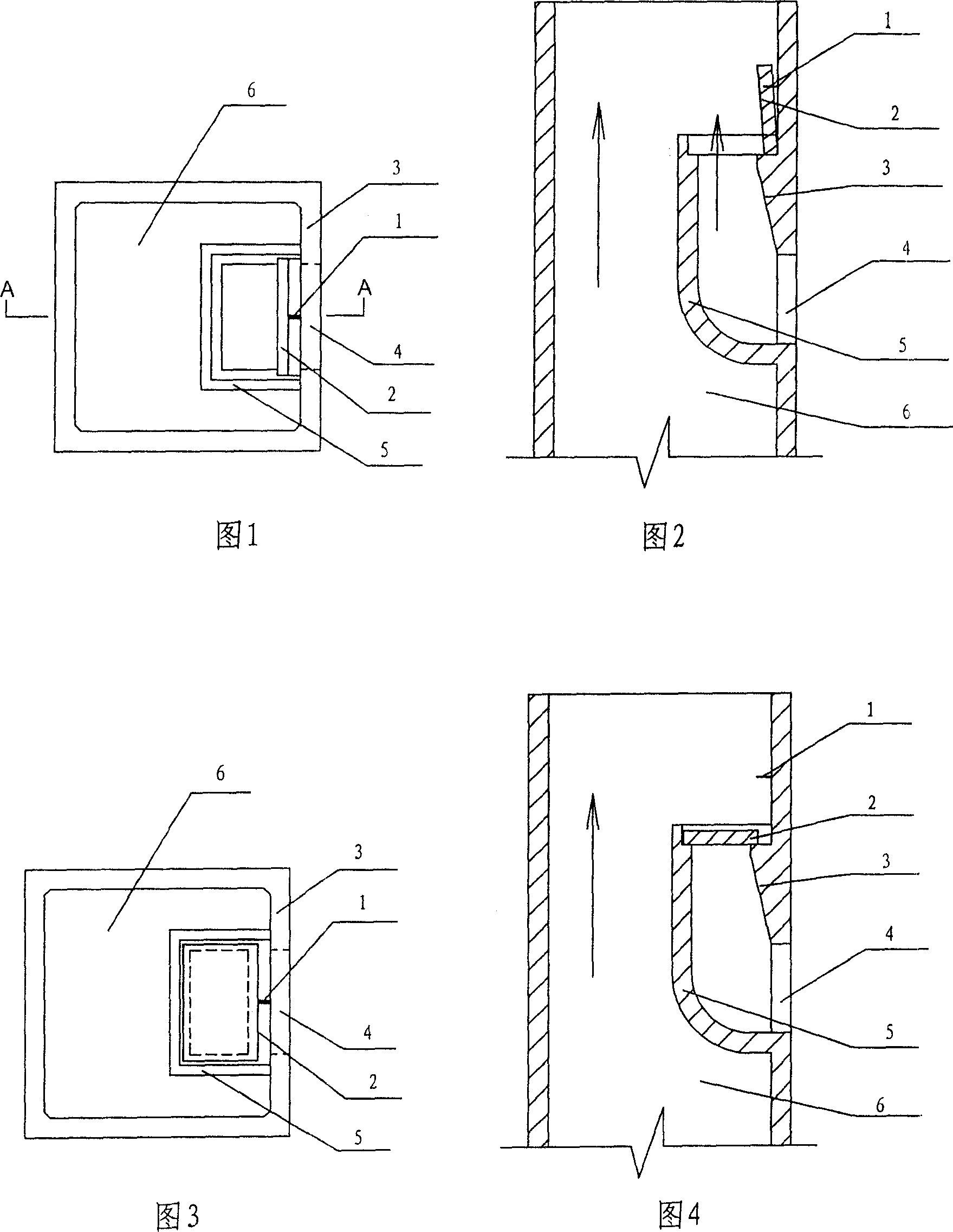
[0018] As shown in Fig. 1 and Fig. 2, the first embodiment is installed in the exhaust pipe 6, and includes a guide pipe structure arranged inside the air inlet 4 of the exhaust pipe. The guide pipe structure in this embodiment is composed of a curved Shaped deflector 5 is a tubular structure surrounded by part of the exhaust pipe wall 3, and the lower end of the guide pipe structure is connected to the air inlet 4 of the exhaust pipe. The deflector 5 in this embodiment is made of cement mortar The guide plate 5 is integrally formed with the homogeneous exhaust pipe wall 3, and a fireproof cover 2 is arranged above the guide pipe structure. The fireproof cover 2 is made of cement mortar, and the fireproof cover 2 is normally It stands upright under working conditions, and its bottom is placed on the platform provided on the exhaust pipe wall 3. Since this part of the exhaust pipe wall 3 and the deflector 5 form a guide pipe structure, the bottom of the fireproof cover 2 It is ...


PUM


Abstract

The invention relates to a special fireproof valve used in kitchen and toilet, wherein it comprises the divert tube at the inner side of gas inlet of ventilate tube; the lower end of divert tube is connected to the gas inlet; the fireproof cover plate is above the divert tube or inside the tube; the bottom of cover plate is put or hinged on the wall of divert tube and via fusion wires is fied on the wall of ventilate tube or divert tube; when the fusion is broken, the fireproof cover plate via gravity will fall back to the top of divert tube or the table of wall of diver tube, to seal the tube. The invention has simple structure, while it can be made from fireproof material or cement, with low cost.

Description

technical field [0001] The invention relates to a fire damper structure specially used for exhaust ducts in kitchens and bathrooms. Background technique [0002] At present, the fire dampers used for kitchen and bathroom exhaust ducts are all independent structures installed on both sides of the exhaust duct inlet. Complicated to make. Contents of the invention [0003] The object of the present invention is to solve the above-mentioned problems existing in the existing fire damper, and provide a special fire damper structure with simple structure and low cost for kitchen and bathroom exhaust ducts. [0004] The object of the present invention is achieved like this: the present invention comprises the guide tube structure that is arranged on the inner side of the air inlet of the exhaust pipe, the lower end of the guide tube structure is connected with the air inlet of the exhaust pipe, above the guide tube structure Or there is an upright fireproof cover in the pipeline...

Claims


Application Information

Patent Timeline
IPC IPC(8): A62C4/02
Inventor 张琦
Owner 深圳市万居科技股份有限公司
Why Eureka
Try Eureka