Anti scrap-jumping device used in high-speed precise punching die

A precision stamping die, anti-jump technology, applied in the direction of perforation tools, manufacturing tools, forming tools, etc., can solve the problem of poor chip removal effect of suction air, so as to save manual anti-jump work, prevent chip jump, The effect of solving the problem of chip jumping

Inactive Publication Date: 2007-05-16
瑞企精密机械(上海)有限公司
View PDF0 Cites 3 Cited by
  • Summary
  • Abstract
  • Description
  • Claims
  • Application Information

AI Technical Summary

Problems solved by technology

However, these methods have great limitations: if a mold master with very skilled experience is required, or limited by machinery and equipment, the effect of suction wind chip removal is not good, etc.

Method used


Image

  • Anti scrap-jumping device used in high-speed precise punching die
  • Anti scrap-jumping device used in high-speed precise punching die
  • Anti scrap-jumping device used in high-speed precise punching die

Examples


Embodiment Construction

[0018] Below in conjunction with accompanying drawing and specific embodiment the present invention is described in further detail:

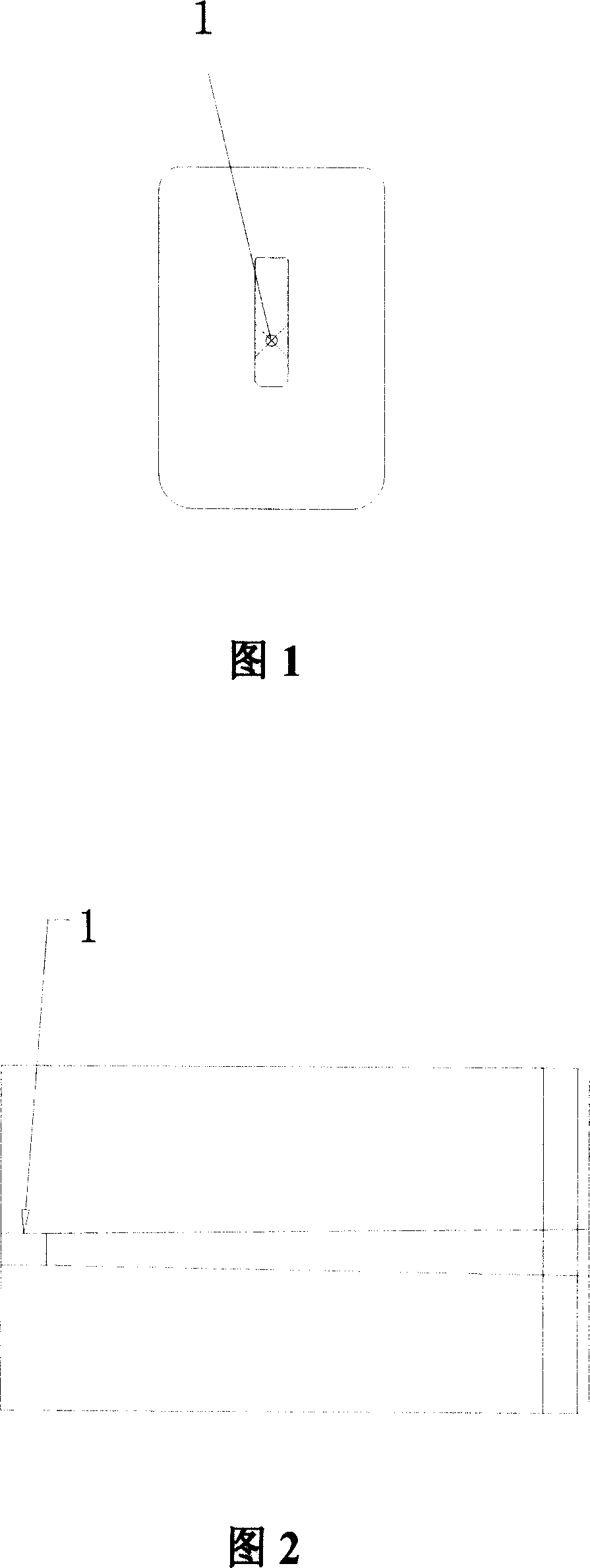
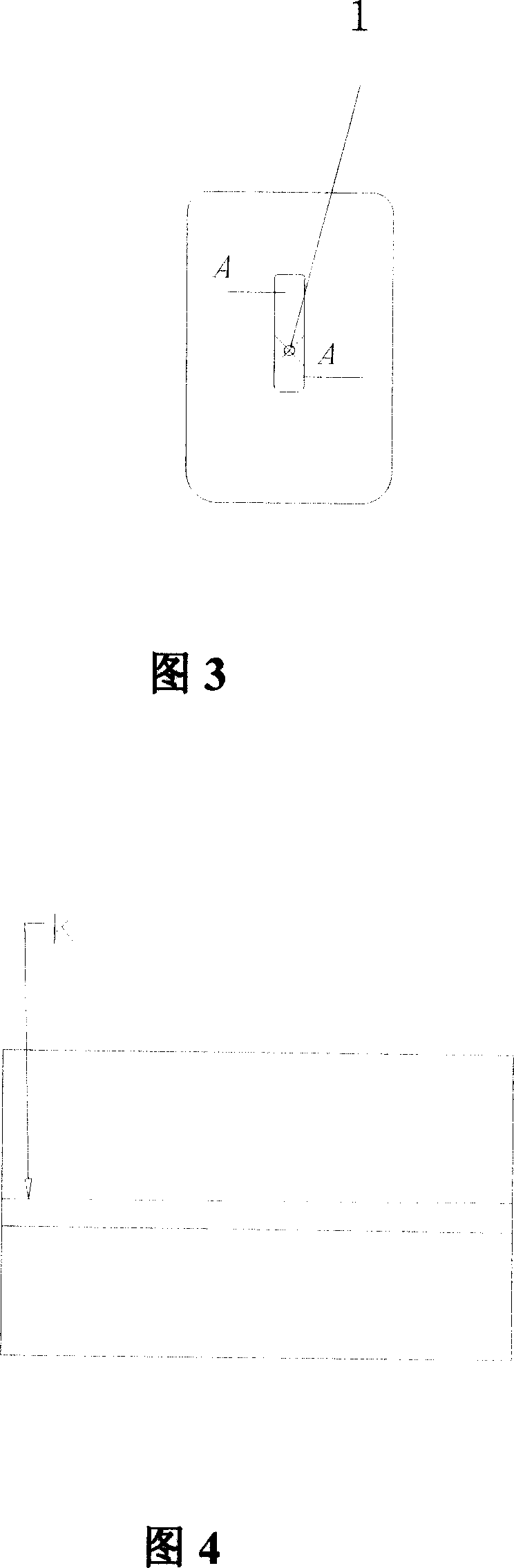
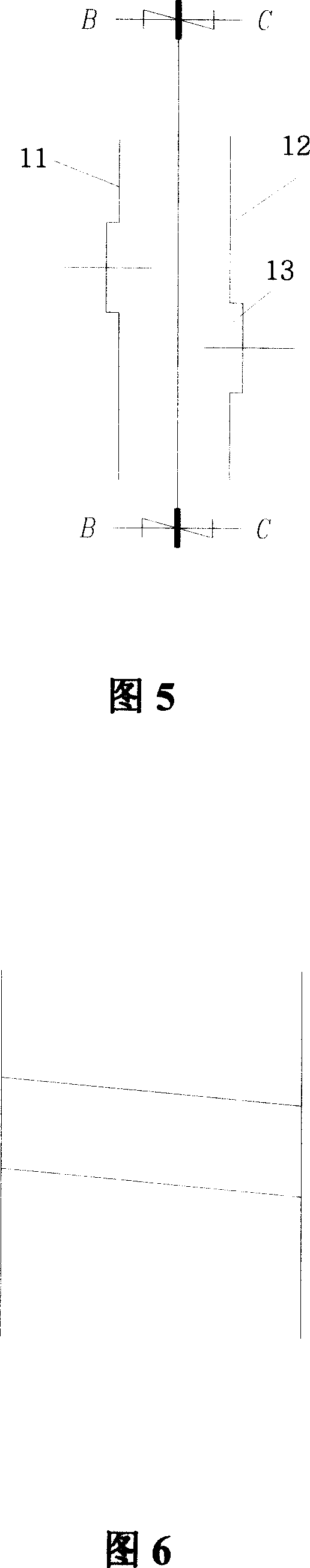
[0019] Visible by Fig. 3, Fig. 4, Fig. 5, Fig. 6, Fig. 7: the present invention comprises punching edge 1; Described punching edge comprises left and right two edges (11,12); , 12) also includes 2-4 gaps 13 with a width of 0.005-0.008mm and a length of 0.5-1.0mm; the relative gaps 13 on the left and right sides (11, 12) are dislocated; the gaps 13 has a slope and the slope of the notch 13 on the left and right two knife edges (11, 12) is opposite;

[0020] The slope is between 2°-3°.

[0021] Due to the addition of the gap, the present invention makes the shape relatively complicated without affecting the shape of the stamped product, even if its resistance increases; and the original straight part of the knife edge is canceled, and the blanking slope is directly added as the cutting edge, so that After the waste material enters the knife edge...


PUM

PropertyMeasurementUnit
Lengthaaaaaaaaaa

Abstract

The invention relates to a fly shred resistor in high-speed punch mould, wherein it comprises the punching blade (1) has left and right two blades (11, 12) with 2-4 cuts (13) at 0.005-0.008mm wide and 0.5-1.0mm long; the cuts are alternated; the cuts (13) have incline while their inclines are reversed. The invention can increase the drawing resistance and torsion force of waste shred, to avoid fly shred.

Description

technical field [0001] The invention relates to a high-speed precision stamping die, in particular to a punching lower die in the high-speed precision stamping die. Background technique [0002] High-speed precision stamping die is a kind of equipment for punching connector terminals in the IT industry. Connector terminals such as: metal connectors in network switches; interface metal connectors in computers include USB, Slot Socket, etc.; Memory cards include metal parts in SD cards and CF cards. [0003] The high-speed precision stamping die has the same structure as the standard eight-plate die of the general die, and the punching die directly determines the quality of the connector terminal. It can be seen from Fig. 1 and Fig. 2 that the punching edge of the existing punching lower die is a long strip. Because of its relatively regular shape, it is a straight part 1 of the knife edge. During the high-speed production process, the speed of mold opening and closing makes...

Claims


Application Information

Patent Timeline
IPC IPC(8): B21D28/34B21D37/12
Inventor 毛忠量
Owner 瑞企精密机械(上海)有限公司
Why Eureka
Try Eureka