
Fiberglass mold

A glass fiber reinforced plastic mold and glass fiber reinforced plastic technology, applied in the field of parts manufacturing, can solve the problems of complex manufacturing process, waste of manpower, lack of any elasticity, etc., to save the repair process, improve product quality, and prevent corners from cracking.

Inactive Publication Date: 2016-03-30
CHONGQING LINZHOU MACHINERY MFG CO LTD
View PDF0 Cites 1 Cited by
  • Summary
  • Abstract
  • Description
  • Claims
  • Application Information

AI Technical Summary

Problems solved by technology

The FRP mold is made by manually laying down FRP fibers layer by layer, and then grinding and correcting them many times. The manufacturing process is relatively complicated, especially for forming lamp holes, assembly holes, structural installation holes and other areas on the mold. The mold body part, the mold body of this part protrudes from the adjacent molding surface, and has a certain inclination angle with the molding surface, the manufacturing process is more complicated, and it is easy to wear, and the mold repair process is very complicated once there is wear and tear
In addition, the texture of the glass fiber reinforced plastic mold is relatively hard, without any elasticity, and the product is easily damaged when the mold is removed
In particular, it is more difficult to mold the mold body of the raised part (the mold body used to form lamp holes, assembly holes, structural mounting holes, etc.), and the corners of the holes often crack, and the post-repair process of the product is very complicated. , waste a lot of manpower, low efficiency, low cost

Method used


Image

  • Fiberglass mold

Examples


Embodiment Construction

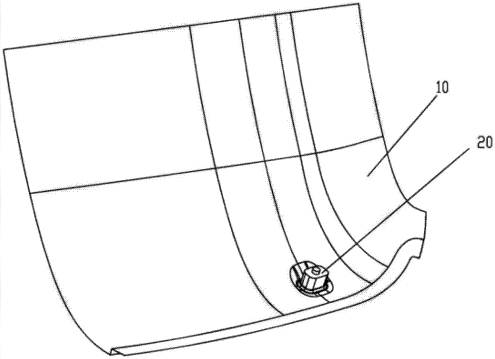
[0007] like figure 1 , a glass fiber reinforced plastic mold, including a main mold 10 and a secondary mold 20, the secondary mold 20 is fixed on the main mold 10 and the molding surface of the secondary mold 20 protrudes from the molding surface of the main mold 10, and the main mold 10 Adopt detachable connection with secondary mold 20. The forming surface in the present invention refers to the surface of the FRP mold used to process the product. The main mold 10 is used to shape the shape of the product, and the secondary mold 20 is used to shape the light holes, assembly holes, structural installation holes, etc. on the product. The secondary mold 20 protrudes on the molding surface of the main mold 10, the shape of the secondary mold 20 matches the shape and size of the hole to be processed, and the secondary mold 20 is generally a block structure. Since the auxiliary mold 20 and the main mold 10 are split structures, the main mold 10 and the auxiliary mold 20 can be pr...


PUM


Abstract

The invention relates to the field of part manufacturing, in particular to a fiberglass mold. The fiberglass mold comprises a main mold body and an auxiliary mold body. The auxiliary mold body is fixed to the main mold body, and the molding face of the auxiliary mold body protrudes out of the molding face of the main mold body; and the main mold body is detachably connected with the auxiliary mold body. The main mold body is used for shaping products, and the auxiliary mold body is used for shaping lamp holes, assembling holes, structural mounting holes and the like in the products; due to the fact that the auxiliary mold body and the main mold body are of split structures, the main mold body and the auxiliary mold body are independently machined, the machining technology of the fiberglass mold is simplified, and precision of the auxiliary mold body cannot be easily ensured; meanwhile, corners of the holes can be effectively prevented from cracking, the product quality is improved, and the subsequent repairing procedure is removed; and in addition, once the auxiliary mold body is worn, the auxiliary mold body can be directly replaced, and the product quality is further improved.

Description

technical field [0001] The invention relates to the field of part manufacturing, in particular to a glass fiber reinforced plastic mold. Background technique [0002] FRP molds can be used to produce composite material products such as automotive interior and exterior trims, instrument panels, vehicle toilets, etc., and have a wide range of uses. The FRP mold is made by manually laying down FRP fibers layer by layer, and then grinding and correcting them many times. The manufacturing process is relatively complicated, especially for forming lamp holes, assembly holes, structural installation holes and other areas on the mold. The mold body part, the mold body of this part protrudes from the adjacent molding surface, and has a certain inclination angle with the molding surface. The manufacturing process is more complicated, and it is easy to wear. Once the mold is worn, the mold repair process is very complicated. In addition, the texture of the glass fiber reinforced plasti...

Claims


Application Information

Patent Timeline
IPC IPC(8): B29C33/30B29C33/40
CPCB29C33/306B29C33/40B29C33/405
Inventor 王子龙
Owner CHONGQING LINZHOU MACHINERY MFG CO LTD
Learn More