
Apparatus for dividing workpiece

Active Publication Date: 2019-04-11
DISCO CORP
View PDF17 Cites 2 Cited by
  • Summary
  • Abstract
  • Description
  • Claims
  • Application Information

AI Technical Summary

Benefits of technology

The present invention provides an apparatus for separating a plate-shaped workpiece into chips while reducing the amount of debris produced during the process. This is achieved by holding one region of the workpiece while pressing another region with a presser, which prevents movement and reduces chippings from the edges of the chips. Ultimately, this invention improves the precision and quality of the chip-dividing process.

Problems solved by technology

Therefore, the chips disposed adjacent to the pressed projected dicing line tend to move away from the area where the projected dicing line is disposed, resulting in chippings produced from the edges of the chips.

Method used


Image

  • Apparatus for dividing workpiece
  • Apparatus for dividing workpiece
  • Apparatus for dividing workpiece

Examples


Embodiment Construction

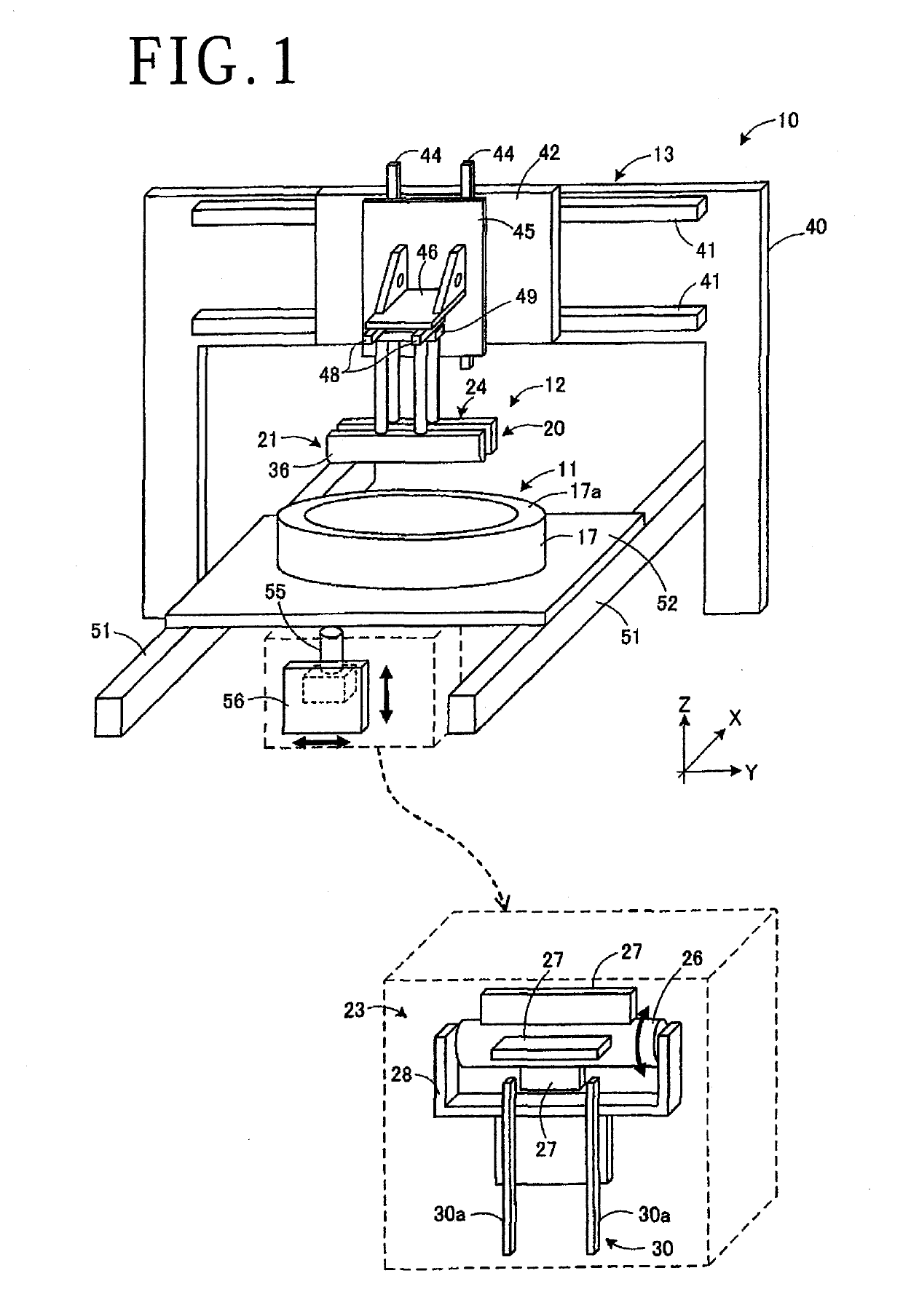
[0018]An apparatus for dividing a plate-shaped workpiece, also referred to as a dividing apparatus, according to an embodiment of the present invention will be described below with reference to the accompanying drawings. FIG. 1 illustrates in perspective the dividing apparatus according to the present invention. The dividing apparatus is not limited to structural details illustrated in FIG. 1, but may be changed or modified in appropriate ways.

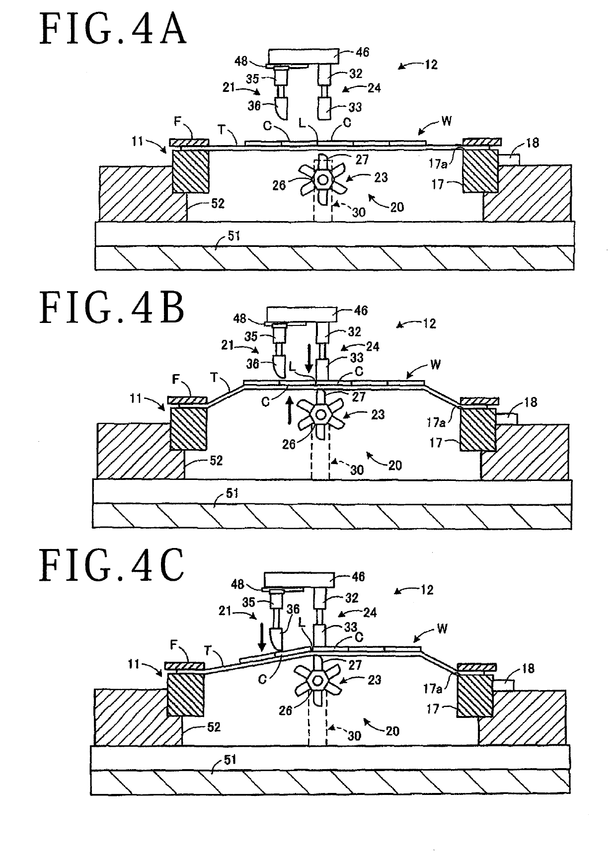
[0019]As illustrated in FIG. 1, a dividing apparatus 10 is arranged to divide, with a dividing unit (dividing means) 12, a plate-shaped workpiece W supported on an annular frame F by a protective tape T into individual chips C (see FIG. 4).

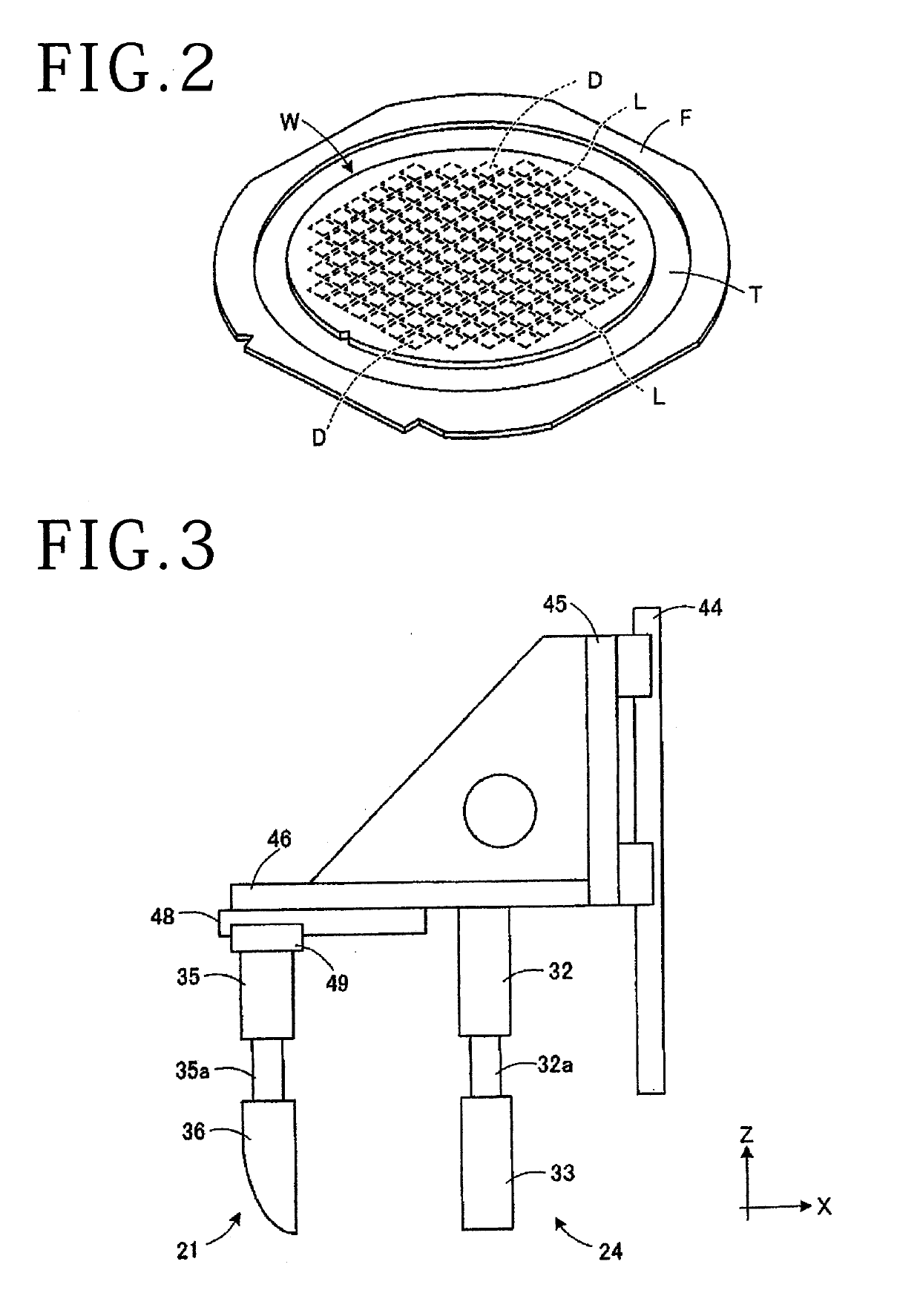
[0020]FIG. 2 illustrates in schematic perspective the workpiece W according to the present embodiment. As illustrated in FIG. 2, the workpiece W has a face side stuck to an upper surface of the protective tape T mounted on the annular frame F and is held on the annular frame F. A tape called mylar tape (not ...


PUM

PropertyMeasurementUnit
Lengthaaaaaaaaaa

Abstract

A dividing apparatus divides a workpiece along projected dicing lines into chips, the workpiece being stuck to an upper surface of a protective tape mounted on an annular frame. The dividing apparatus includes a frame holding unit for holding the annular frame and a dividing unit for pressing the workpiece in the vicinity of one at a time of the projected dicing lines and dividing the workpiece into chips along the projected dicing line. The dividing unit includes a holder for holding a portion of the workpiece in the vicinity of the projected dicing line where the workpiece is to be broken, from both upper and lower surfaces of the workpiece, and a presser for pressing chips next to chips held by the holder across the projected dicing line where the workpiece is to be broken, thereby to divide the workpiece along the projected dicing line.

Description

BACKGROUND OF THE INVENTIONField of the Invention[0001]The present invention relates to an apparatus for dividing a plate-shaped workpiece into chips by applying external forces thereto along projected dicing lines on the workpiece.Description of the Related Art[0002]Plate-shaped workpieces or substrates made of sapphire, SiC, glass, or the like are divided along projected dicing lines thereon into individual pieces. For dividing a workpiece, for example, a laser beam is applied to the workpiece along projected dicing lines thereon from a face side of the workpiece, forming modified layers along the projected dicing lines in the workpiece. After the modified layers have been formed, the workpiece is divided according to a three-point breaking process using a breaking apparatus having a blade or pressing member, as disclosed in Japanese Patent Laid-Open No. 2009-148982. According to the disclosed three-point breaking process, the blade presses the workpiece along the projected dicing...

Claims


Application Information

Patent Timeline
IPC IPC(8): H01L21/67H01L21/687B28D5/00
CPCH01L21/67092H01L21/687B28D5/0011B28D5/0082H01L2221/68327H01L21/6836H01L21/78H01L21/67132H01L21/681B28D5/0023B28D5/0029B28D5/0088H01L2221/68336B28D5/0052C03B33/02
Inventor MIHAI, CHRISKANEOKA, KAZUKITAKAHARA, TAKUSHIHIRATE, MAKOTO
Owner DISCO CORP
Learn More