Examining apparatus for spot weld of steel shade thread

A technology of detectors and steel cords, applied in instruments, measuring devices, scientific instruments, etc.

Active Publication Date: 2007-05-16
JIANGSU XINGDA STEEL TYPE CORD
View PDF0 Cites 10 Cited by
  • Summary
  • Abstract
  • Description
  • Claims
  • Application Information

AI Technical Summary

Problems solved by technology

Whether the solder joint is qualified directly affects the quality of the steel cord. The quality requirements of the solder joint include the appearance and the breaking force it can withstand. The appearance can be

Method used


Image

  • Examining apparatus for spot weld of steel shade thread
  • Examining apparatus for spot weld of steel shade thread

Examples


Embodiment Construction

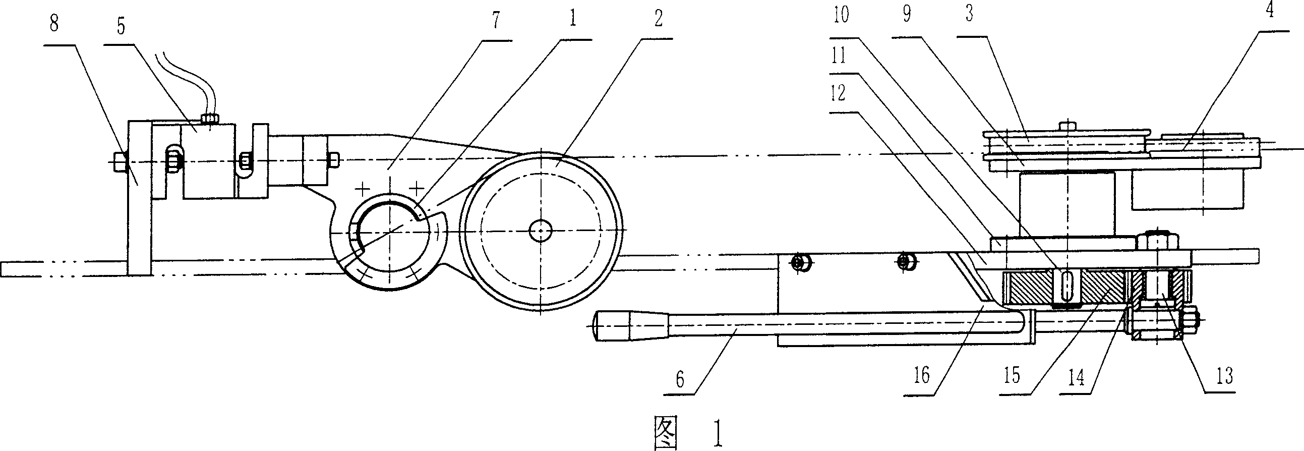
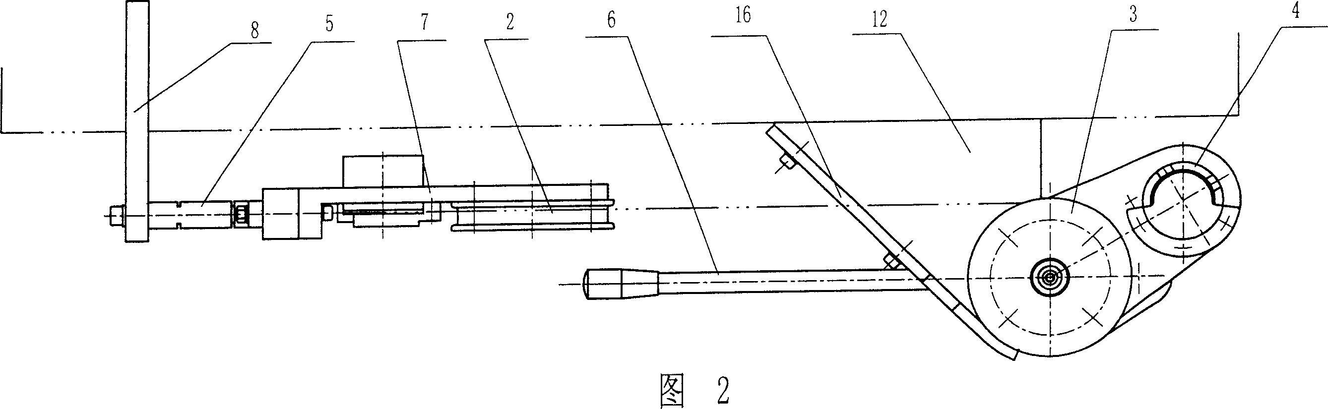
[0009] According to Fig. 1 and shown in Fig. 2, the present invention mainly is made up of left clamp 1, right clamp 4, left reel 2, right reel 3, load cell 5 and operating handle 6. The left clamp 1 and the left reel 2 are fixed on the wheel frame 7, the left end of the wheel frame 7 is fixed to the connecting plate 8 by the load cell 5, the wheel frame 7 is in a vertical state, the signal output line of the load cell 5 is connected to the Indicators are connected. The right winding wheel 3 and the right clamp 4 are fixed on the follower plate 9, and the follower plate 9 is horizontally installed on the upper end of the rotating shaft 10. The rotating shaft 10 is supported by bearings in an axle seat 11 , and the axle seat 11 is mounted on a horizontal support plate 12 . The rotating shaft 10 is connected with the operating handle 6 through a transmission member, and the transmission member includes a pin shaft 13 , a driving gear 14 and a driven gear 15 . The lower end of ...


PUM


Abstract

This invention discloses one steel string weld points test machine, which comprises weight sensor, left clamper, left roller wheel, right clamper, right roller wheel and operation handle, wherein, the left clamper and roller wheel are fixed on wheel rack and right clamper and right roller wheel are fixed on random board fixed on rotation axis connected to operation handle through drive parts; the said rack is fixed with weight sensor and the left and right roller wheel work tank surface and weight sensor axis line are tangent with signal output wires connected to indicator.

Description

technical field [0001] The invention relates to a steel cord welding spot detector. Background technique [0002] During the production of radial tires, the steel cords used for radial tires must reach the specified length, but sometimes the specified length cannot be reached during the twisting process of the steel cords, so the short steel cords must be welded to the specified length. Whether the solder joint is qualified directly affects the quality of the steel cord. The quality requirements of the solder joint include the appearance and the breaking force it can withstand. The appearance can be visually inspected and measured, but there is no special equipment to detect how much tension the solder joint can withstand. Without breaking, so as to judge whether the solder joint meets the quality requirements. Contents of the invention [0003] In view of the above problems, the present invention provides a steel cord welding spot detector, which can determine whether th...

Claims


Application Information

Patent Timeline
IPC IPC(8): G01N3/08G01N3/04
Inventor 刘祥董玉华
Owner JIANGSU XINGDA STEEL TYPE CORD
Why Eureka
Try Eureka