

Adsorption apparatus
A technology of adsorption device and buffer device, applied in nonlinear optics, instruments, optics, etc., can solve problems such as damage to a plate-shaped workpiece 10, reduce pressure loss, avoid scratches or electrostatic discharge, and reduce the probability of damage Effect
- Summary
- Abstract
- Description
- Claims
- Application Information
AI Technical Summary
Problems solved by technology
Method used
Image

Examples
Embodiment Construction
[0045] In order to have a further understanding and understanding of the structural features and the achieved effects of the present invention, I would like to provide a preferred embodiment and a detailed description, as follows:
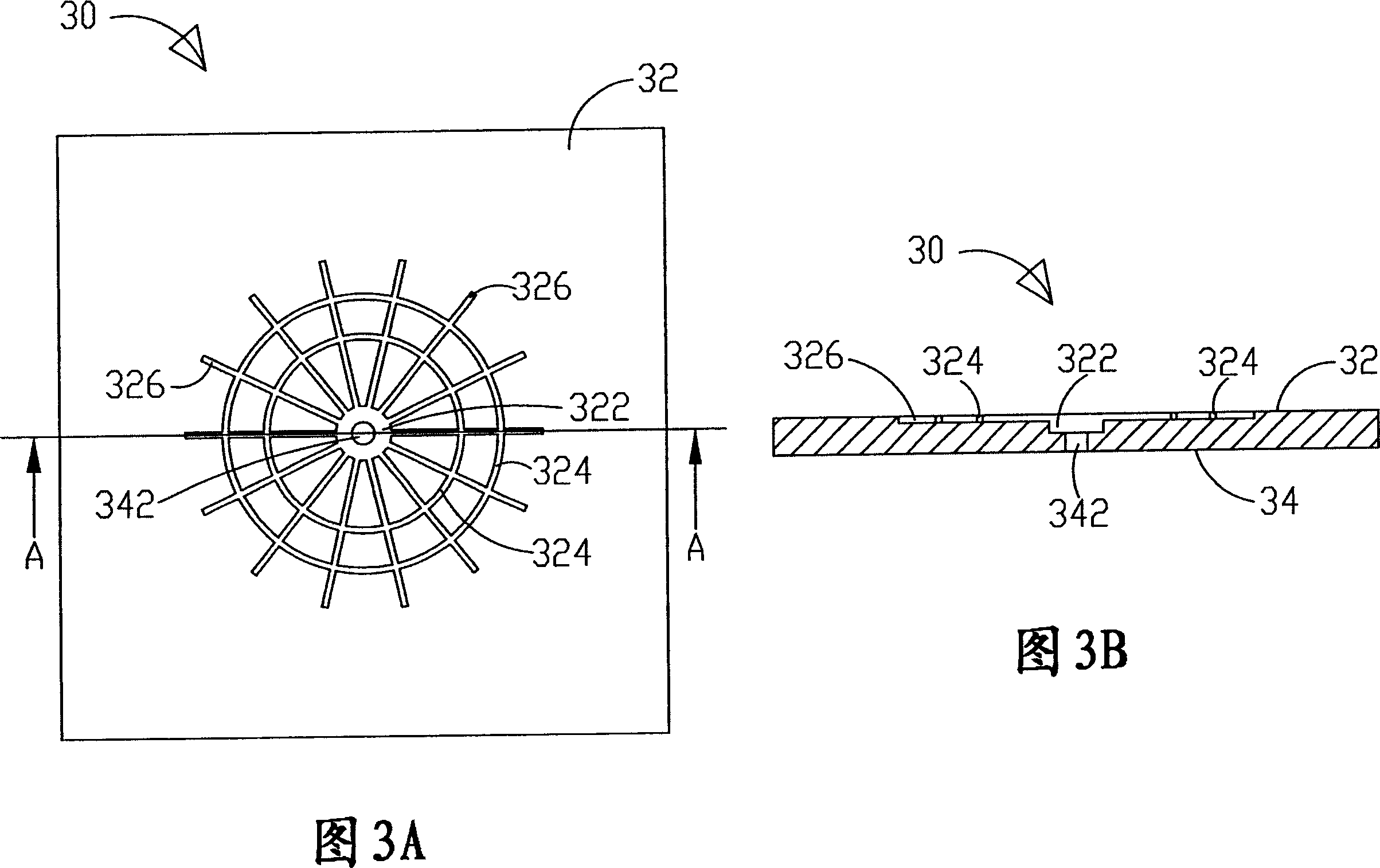
[0046] Please refer to Fig. 3A and Fig. 3B, which is a schematic structural view of a preferred embodiment of the present invention and a sectional view along the A-A direction of Fig. 3A; as shown in the figure, the adsorption device of the present invention includes a body 30, a groove 322, and a hole 342, a plurality of annular grooves 324 and at least linear grooves 326; the body 30 has a first side 32 and a second side 34 facing away from the first side 32; the groove 322 is located on the first side 32; the hole 342 Located on the second side 34, and the hole 342 runs through the groove 322; a plurality of annular grooves 324 are formed on the first side 32, and the plurality of annular grooves 324 communicate with the groove 322; the linear g...
PUM
 Abstract
Description
Claims
Application Information