Bone anchoring device

An anchoring device and anchoring technology, applied in the direction of fixators, external fixators, internal fixators, etc., can solve problems such as restrictions

Active Publication Date: 2007-05-23
BIEDERMANN TECH GMBH & CO KG
View PDF3 Cites 16 Cited by
  • Summary
  • Abstract
  • Description
  • Claims
  • Application Information

AI Technical Summary

Problems solved by technology

However, the possibility to adjust the position of the head to the anatomy is limited

Method used


Image

  • Bone anchoring device
  • Bone anchoring device
  • Bone anchoring device

Examples


Embodiment Construction

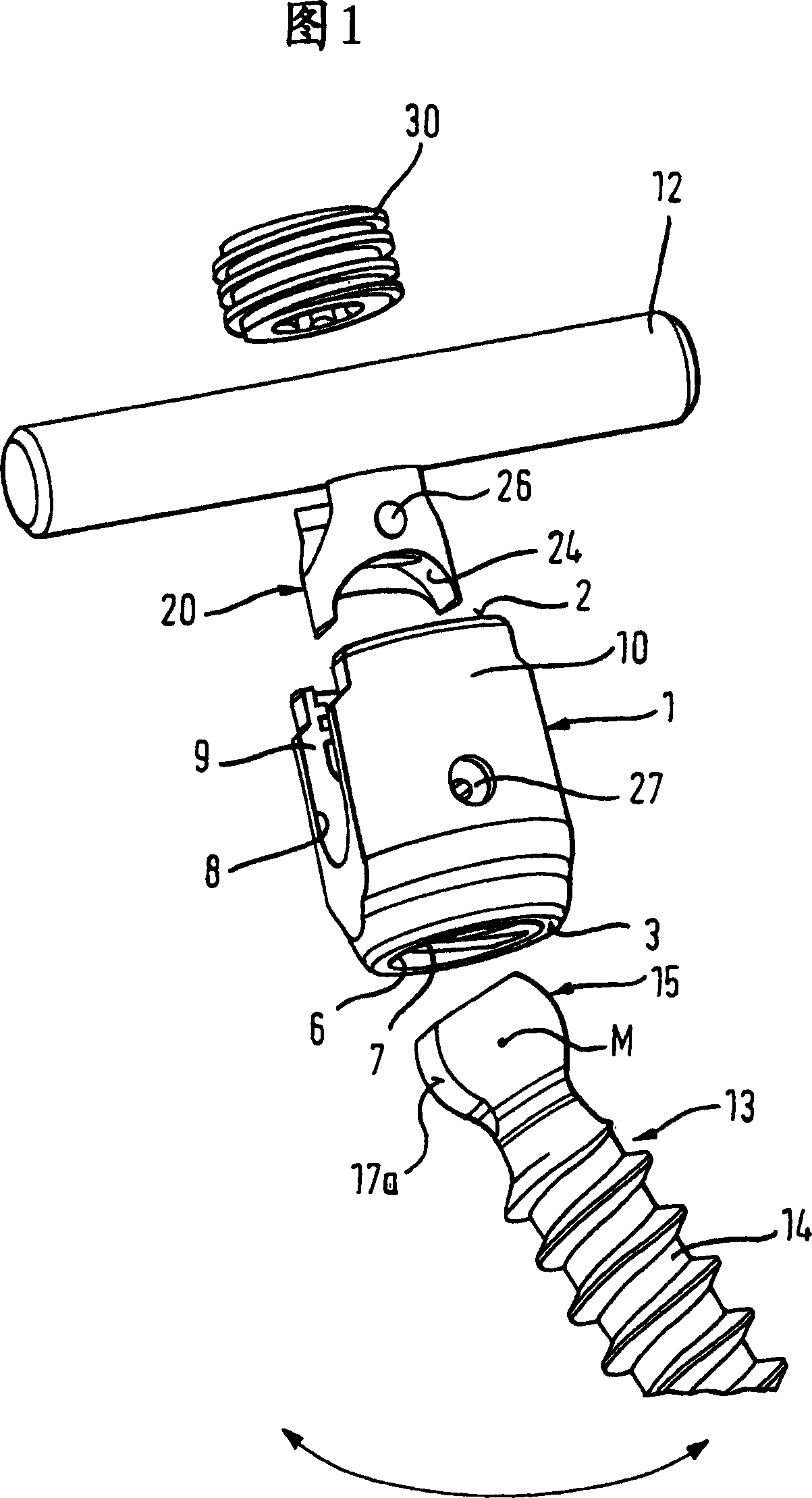
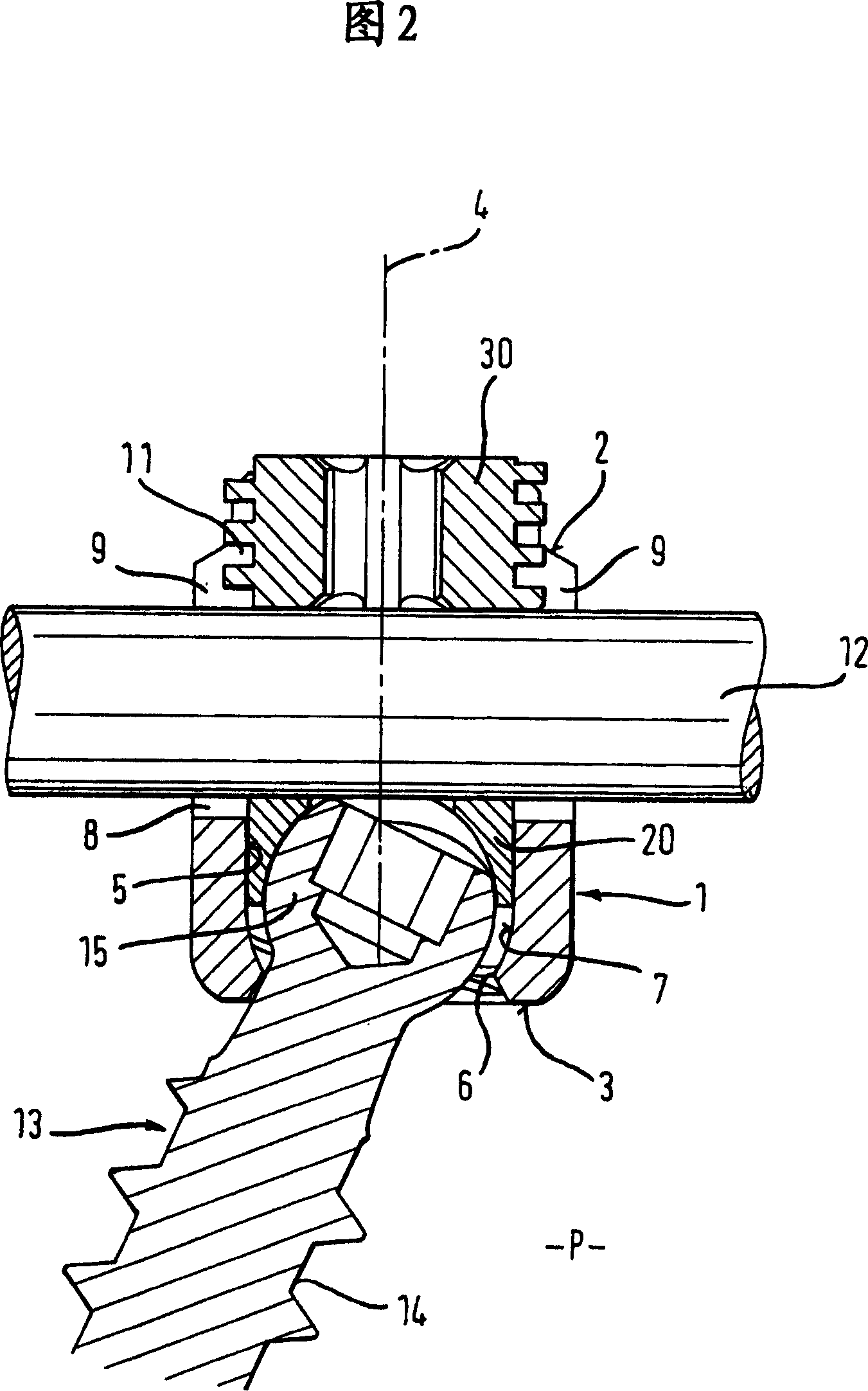
[0028] As shown in Figures 1 and 2, the bone anchoring device comprises a receptacle 1 which is generally cylindrical and has a first end 2 and a second end 3 opposite the first end. Both ends extend perpendicular to the longitudinal axis 4 . Coaxially with the longitudinal axis 4 there is provided a bore 5 extending from the first end 2 to a predetermined distance from the second end 3 . An opening 6 is provided at the second end 3 , the diameter of which is smaller than the diameter of the hole 5 . The coaxial bore 5 tapers towards the opening 6 in the portion 7 , which may be, for example, spherical or conical in shape.

[0029] The receiving part 1 also comprises a U-shaped recess 8 starting from the first end part 2 and extending in the direction of the second end part 3 to a predetermined distance from said second end part 3 . Two free legs 9 , 10 are formed by means of the U-shaped recess 8 , which extend toward the first end 2 . Close to the first end 2 , the recept...


PUM


Abstract

A bone anchoring device is provided comprising a receiving part (1) for receiving a rod, the receiving part having a first bore (1) coaxial with a longitudinal axis (4) and a second bore (6), and an anchoring element having a first end (14) for insertion into the bone and a second end (15) positionable within a second bore (6), the anchoring element (13) being movable relative to the receiving part (1) in limited angular range about the longitudinal axis (4), the angles lying in a single plane (P); and a fixation element (30) cooperating with the receiving part (1) to lock the anchoring element (13) relative to the receiving part (1). The anchoring element (13) is pivotable relative to the receiving part (1) around one rotational axis transverse to the longitudinal axis (4).

Description

technical field [0001] The invention relates to a bone anchoring device comprising an anchoring element to be anchored in a bone and a receptacle for receiving a rod to be connected to the anchoring element, wherein the receptacle has a first hole and a second hole coaxial with the longitudinal axis , the anchoring element has a first end for insertion into the bone and a second end positionable within the second hole, and the anchoring element is movable within a limited angular range relative to the receiving portion around the longitudinal axis of the receiving portion . The anchoring element is pivotable relative to the receiver about a single axis of rotation transverse to the longitudinal axis of the receiver. Thus, the anchoring element is adjustable relative to the receptacle in a single plane. Background technique [0002] US 5,005,562 discloses a bone anchoring device having a threaded shaft or hook to be anchored in bone and a head integrally formed with said sh...

Claims


Application Information

Patent Timeline
Patent Type & Authority Applications(China)
IPC IPC(8): A61B17/64A61B17/58
CPCA61B17/8605A61B17/7038A61B17/7032A61B17/7037A61B17/7004A61B17/58A61B17/86
Inventor L·比德曼W·马蒂斯
Owner BIEDERMANN TECH GMBH & CO KG
Why Eureka
Try Eureka