Sewing machine

A sewing machine and air supply mechanism technology, which is applied in the field of sewing machines, can solve the problems of poor cooling efficiency of the shuttle shaft, adverse effects of stitch formation, and heating of the bottom plate, etc.

Inactive Publication Date: 2007-05-23
BROTHER KOGYO KK
View PDF0 Cites 1 Cited by
  • Summary
  • Abstract
  • Description
  • Claims
  • Application Information

AI Technical Summary

Problems solved by technology

Therefore, the cooling efficiency of the hook shaft is poor, and the bottom plate also generates heat.
The wind sent from the cooling fan goes over the drive motor and the hook shaft until it reaches the rotary hook, which will cause the upper and lower threads to swing when the stitches are formed, resulting in the formation of stitches that cannot be formed and so-called skipped stitches. Problems with adverse effects

Method used


Image

  • Sewing machine
  • Sewing machine
  • Sewing machine

Examples


Embodiment Construction

[0014] An embodiment in which the present invention is applied to a zigzag sewing machine will be described below with reference to the accompanying drawings.

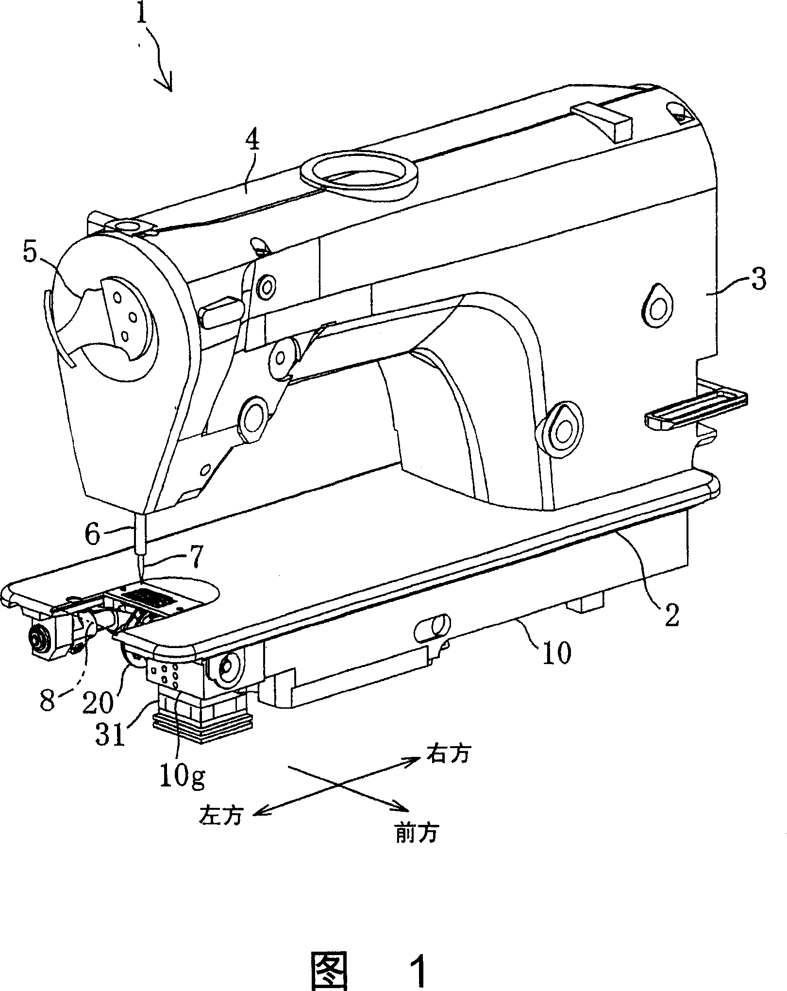
[0015] As shown in FIG. 1 , the zigzag sewing machine 1 has a bottom plate 2 , a column 3 standing upright from the right end of the bottom plate 2 , and a casing extending leftward from the upper end of the column 3 facing the bottom plate 2 . part 4. This zigzag sewing machine 1 is fixed on a workbench 9 .

[0016] The casing part 4 is equipped with a sewing machine main shaft (not shown), a needle bar up and down drive mechanism, a rotary thread take-up mechanism (not shown), and the like. The main shaft of the sewing machine is arranged along the left and right directions, and a sewing machine motor (not shown) drives the main shaft of the sewing machine to rotate. The needle bar up and down drive mechanism makes the needle bar 6 with the sewing needle 7 installed at the lower end move up and down. The rotary th...


PUM


Abstract

The sewing machine of the invention comprises: a bottom portion, a oil pan arranged under this bottom, a rotary shuttle arranged in the interior of the bottom portion, a shuttle axis connects to the rotary shuttle by end, a shuttle axis supporting portion which can support rotatablely the shuttle axis arranged in the interior of the bottom portion, as well as a blower that is used to cool the shuttle axle, the blower is characterized by being provided with an opening portion formed on the wall of the oil pan described, and a blower, the form of which is used to jam the opening portion arranged upon the oil pan, the blower is utilized to blow to the shuttle axis supporting portion of the bottom portion.

Description

technical field [0001] The present invention relates to a sewing machine that cools a hook shaft that drives a hook to rotate by using an air blowing mechanism provided on an oil pan under a bottom plate portion. Background technique [0002] Conventionally, in various sewing machines such as a zigzag sewing machine, a needle bar up and down driving mechanism is provided at the front end of the housing portion, and a hook mechanism composed of a hook and a hook shaft for driving the hook to rotate is provided inside the bottom plate. In this sewing machine, the hook tip of the rotary hook is used to hook the upper thread extending from the eyelet of the sewing needle installed at the lower end of the needle bar to form an upper thread loop, and the stitches are formed by twisting the upper thread and the lower thread. . [0003] The rotary hook has an inner shuttle for accommodating a bobbin case and an outer shuttle for rotatably supporting the inner shuttle. A shuttle oi...

Claims


Application Information

Patent Timeline
Patent Type & Authority Applications(China)
IPC IPC(8): D05B71/00
Inventor 宫崎耕太郎梅田和俊加藤雅史
Owner BROTHER KOGYO KK
Why Eureka
Try Eureka