Method for reducing leakage in liquid conveying system
A conveying system and liquid technology, applied in pipeline systems, gas/liquid distribution and storage, mechanical equipment, etc., can solve the problems of high cost, environmental pollution, waste of raw materials, etc.
Inactive Publication Date: 2007-05-23
河南中轴集团有限公司
View PDF0 Cites 3 Cited by
- Summary
- Abstract
- Description
- Claims
- Application Information
AI Technical Summary
Problems solved by technology
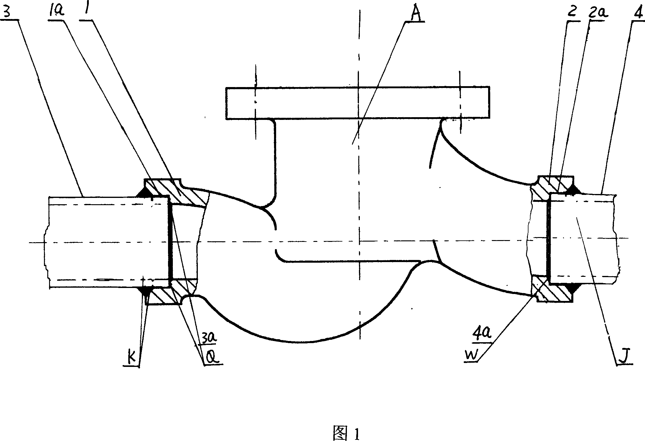
[0002] In order to control the flow of industrial pipelines, some valves must be installed between the pipelines. The valves used are all castings, with a flange at the outlet and inlet. The connection between the valve body and the pipeline is Connect the flange on the valve body and the flange welded at the end of the pipeline with nuts and bolts. In order to prevent the leakage of the conveyed material, the flange at the end of the valve body and the flange at the end of the pipeline A gasket must be placed between the discs. This connection method between the valve body and the pipeline is necessary for pipelines that require frequent replacement of valves, but for pipelines that do not require frequent replacement of valves, flanged The valve body is not only cumbersome and expensive, but also if liquid is transported in the pipeline, this connection will often cause liquid leakage at their contact points, which not only wastes the raw materials being transported, but also pollutes the environment
Method used
View moreImage
Smart ImageViewing Examples
Examples
Embodiment
[0010] Embodiment: The method for reducing the leakage in the liquid conveying system is: first process an annular step in the outlet end and the inlet end of the valve body, and connect the end faces of the inserted liquid inlet pipe and the liquid outlet pipe with the annular step respectively. The bottom surfaces are in contact, and then the inlet and outlet pipes of the inlet and outlet pipes of the valve body are welded together.
Login to View More PUM
 Abstract
Inserting the in and out ports of the valve of the liquid delivery system into the in and out liquid channel, fastening them together, it can ensure the tightness of the connection between the pipe and the valve, reducing the leaking point of the valve and the contact point of the pipe. It is light, reduced in cost by saving the original flange disk, and easy for construction.
Description
technical field [0001] The invention belongs to a method for reducing leakage in a liquid delivery system, in particular to a method for reducing leakage in a delivery system containing valves and pipelines. Background technique [0002] In order to control the flow of industrial pipelines, some valves must be installed between the pipelines. The valves used are all castings, with a flange at the outlet and inlet. The connection between the valve body and the pipeline is Connect the flange on the valve body and the flange welded at the end of the pipeline with nuts and bolts. In order to prevent the leakage of the conveyed material, the flange at the end of the valve body and the flange at the end of the pipeline A gasket must be placed between the discs. This connection method between the valve body and the pipeline is necessary for pipelines that require frequent replacement of valves, but for pipelines that do not require frequent replacement of valves, flanged The valve...
Claims
Login to View More Application Information
Patent Timeline
 IPC IPC(8): F17D5/02
Inventor 李国玉温国旭
Owner 河南中轴集团有限公司
Features
- R&D
- Intellectual Property
- Life Sciences
- Materials
- Tech Scout
- Unparalleled Data Quality
- Higher Quality Content
- 60% Fewer Hallucinations
Learn More Browse by: Latest US Patents, China's latest patents, Technical Efficacy Thesaurus, Application Domain, Technology Topic, Popular Technical Reports.
© 2025 PatSnap. All rights reserved.Legal|Privacy policy|Modern Slavery Act Transparency Statement|Sitemap|About US| Contact US: help@patsnap.com

