
Light conducting board

A light guide plate and light incident surface technology, applied in the field of light guide plate, can solve the problems of not being able to meet the requirements of use, unable to converge the light, and unable to converge the light of the light guide plate

Inactive Publication Date: 2007-05-23
HONG FU JIN PRECISION IND (SHENZHEN) CO LTD +1
View PDF0 Cites 2 Cited by
  • Summary
  • Abstract
  • Description
  • Claims
  • Application Information

AI Technical Summary

Problems solved by technology

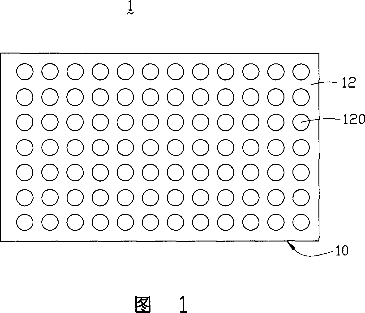
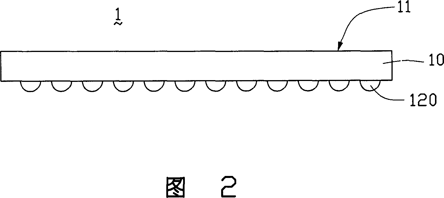
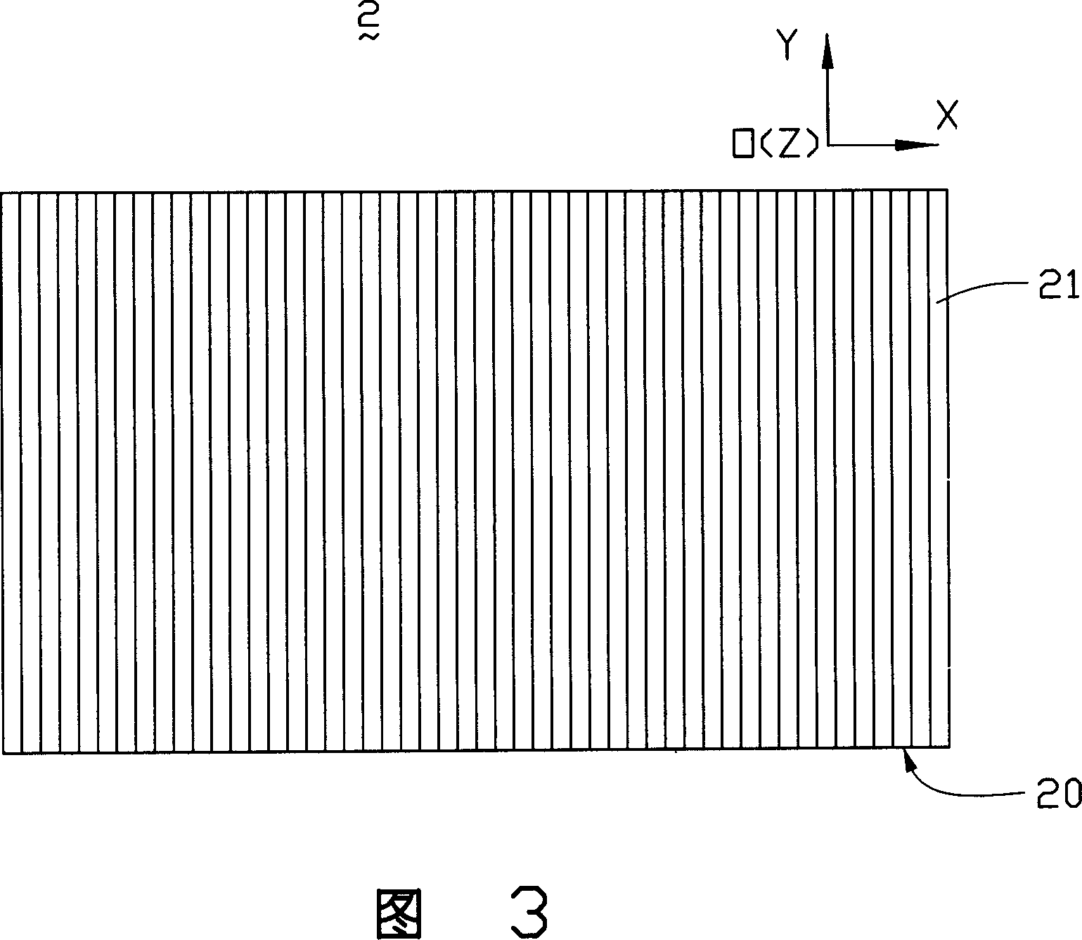
However, the light guide plate 2 with this structure can only converge the light in the left and right directions of the extension direction of the V-shaped groove 210. Angle convergence is performed in the extension direction of the groove 210, that is, the light cannot be converged in the direction of the YOZ plane close to the Z axis
Therefore, part of the light emitted from the light-emitting surface 21 of the light guide plate 2 cannot be converged in a direction perpendicular to the light-emitting surface 21, that is, most of the light cannot be vertically incident on the liquid crystal display.
[0006] Since the light guide plates of the above two structures cannot converge the light in a direction perpendicular to the light-emitting surface in all directions, that is, they cannot make the light vertically incident on the liquid crystal display, so they cannot meet the requirements of use.

Method used


Image

  • Light conducting board
  • Light conducting board
  • Light conducting board

Examples


Embodiment Construction

[0019] The present invention will be described in further detail below in conjunction with the accompanying drawings.

[0020] Please refer to FIG. 5 , FIG. 6 and FIG. 7 together. The light guide plate 3 according to the first embodiment of the present invention is a flat light guide plate made of transparent resin material, such as polymethyl methacrylate or polycarbonate. The light guide plate 3 has two light incident surfaces 30 , a light exit surface 31 intersecting the light incident surfaces 30 , and a bottom surface 32 opposite to the light exit surfaces 31 . The bottom surface 32 of the light guide plate 3 is a plane. The light emitting surface 31 of the light guide plate 3 is provided with several rib groups 310 parallel to the light incident surface 30 and several rib groups 311 perpendicular to the light incident surface 30. The areas of the surfaces 31 are equal, the rib groups 310 parallel to the light incident surface 30 and the rib groups 311 perpendicular to t...


PUM


Abstract

The invention relates to an illuminator including an entry surface, an emitting surface and a bottom surface correspond to the emitting surface. Among them, the emitting surface is equipped with a number of prism groups parallel to the entry surface and a number of prism groups vertical to the entry surface. They are staggered distributed. Each prism groups has a number of prisms. Prism groups parallel to the entry surface make light converges in the transverse direction of entry surface extension. Prism groups vertical to the entry surface make light converges in the direction of entry surface extension. Therefore, the illuminator can make light converge in all direction, and make the incident light perpendicular to the LCD.

Description

【Technical field】 [0001] The invention relates to a light guide plate, in particular to a light guide plate capable of converging light in all directions and vertically incident on a liquid crystal display. 【Background technique】 [0002] Since the liquid crystal itself of the liquid crystal display panel does not have light-emitting characteristics, in order to achieve the display effect, it is necessary to provide a surface light source device for the liquid crystal display panel, such as a backlight system, whose function is to supply a surface light source with sufficient brightness and uniform distribution to the liquid crystal display panel. [0003] The backlight system in the prior art is mainly composed of a light source, a light guide plate, a reflection plate, a diffuser plate and a prism plate. The light source can be arranged on one side or two opposite sides of the light guide plate and emit light to the light guide plate. The function of the light guide plate...

Claims


Application Information

Patent Timeline
IPC IPC(8): G02F1/1335
Inventor 廖明毅
Owner HONG FU JIN PRECISION IND (SHENZHEN) CO LTD
Features
  • Generate Ideas
  • Intellectual Property
  • Life Sciences
  • Materials
  • Tech Scout
  • Unparalleled Data Quality
  • Higher Quality Content
  • 60% Fewer Hallucinations
Learn More