Heat radiator for elevator hoistway

A heat dissipation device and elevator shaft technology, applied in the energy efficiency of elevators, elevators in buildings, transportation and packaging, etc., can solve the problems of large power consumption, large devices, high installation costs and high operating costs, and achieve efficient absorption, Effect of preventing temperature rise

Inactive Publication Date: 2007-05-23
MITSUBISHI ELECTRIC CORP
View PDF1 Cites 5 Cited by
  • Summary
  • Abstract
  • Description
  • Claims
  • Application Information

AI Technical Summary

Problems solved by technology

[0004] However, in the conventional air conditioner for an elevator as described above, a refrigeration unit is required, and the device

Method used


Image

  • Heat radiator for elevator hoistway
  • Heat radiator for elevator hoistway
  • Heat radiator for elevator hoistway

Examples


Embodiment 1

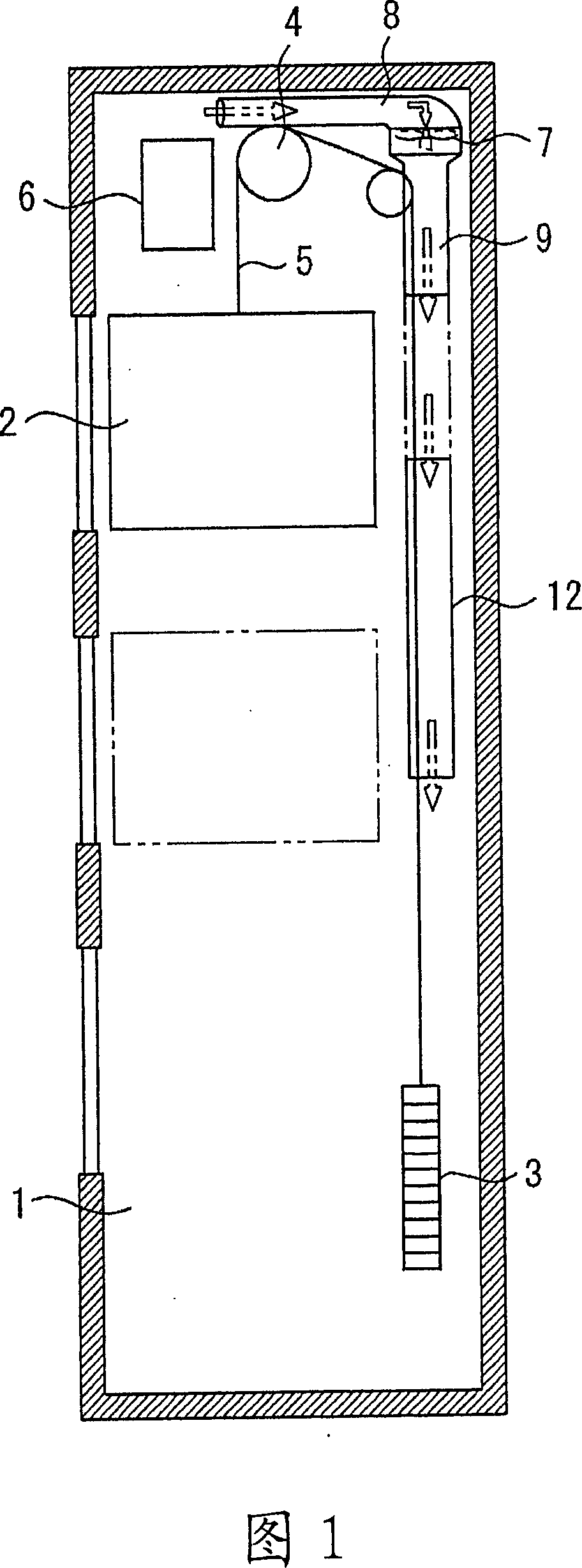
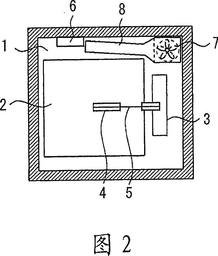
[0026] Fig. 1 and Fig. 2 are longitudinal sectional views and plan views showing a heat radiation device for an elevator shaft according to Embodiment 1 of the present invention. The elevator device of the present invention is a so-called machine-roomless elevator, which includes the following parts: the car 2 of the elevator, which travels along the guide rails in the hoistway 1; 2 running in the opposite direction; the driving device 4, which is arranged in the upper part of the hoistway 1; the rope 5, which connects the car 2 and the counterweight 3 at both ends, and is wound on the driving device 4; and the control device 6, It is arranged on a side wall of the upper part in the hoistway 1 and is used for controlling the driving device 4 . That is, the driving device 4 and the control device 6 , which tend to increase in temperature due to the released heat, are arranged in the upper part of the hoistway 1 .

[0027] In addition, an air blower 7 is provided at an upper co...

Embodiment 2

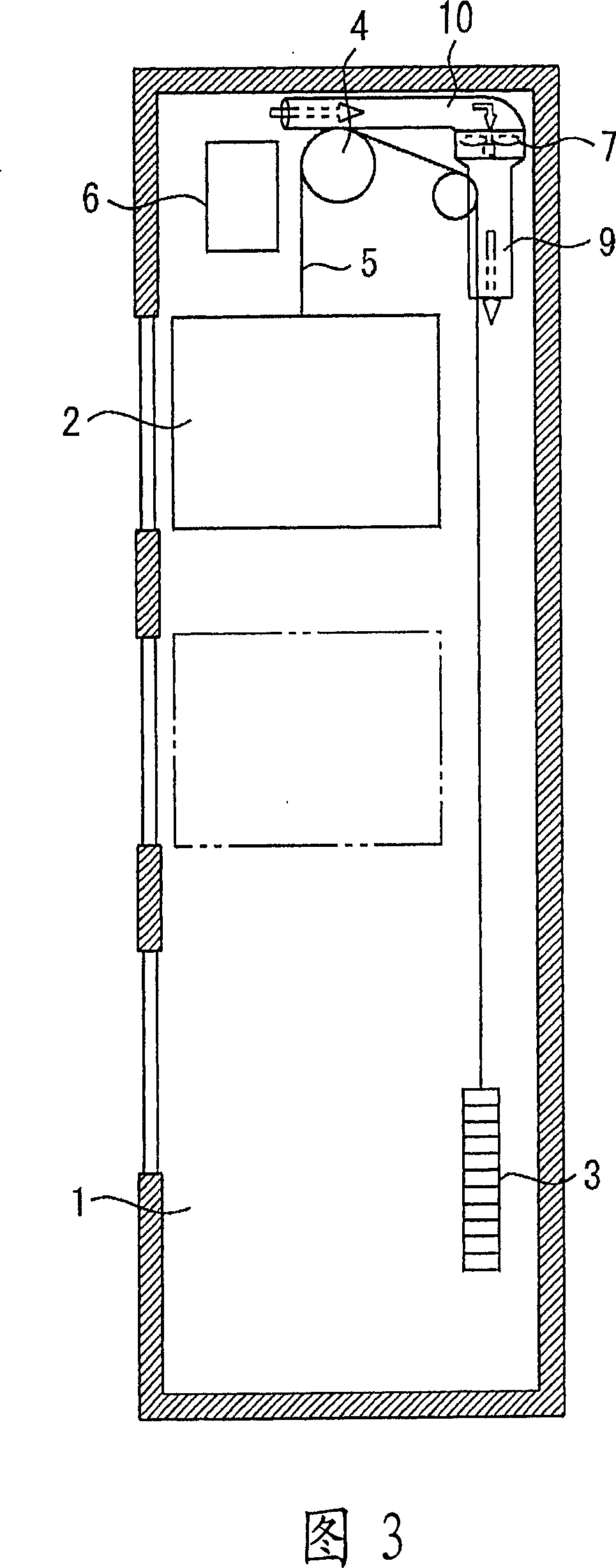
[0033] Fig. 3 and Fig. 4 are longitudinal sectional views and plan views showing a heat radiation device for an elevator shaft according to Embodiment 2 of the present invention.

[0034] In the above-mentioned Embodiment 1, the air inlet of one end of the air intake pipe 8 installed on the air intake side of the blower 7 is configured to come near the top of the control device 6, but in this Embodiment 2, the air inlet installed on the air intake of the blower 7 One end air intake of the air intake pipe 10 on the side is disposed near the driving device 4 . Other configurations are the same as those in Example 1.

[0035] In the heat dissipation device of the elevator hoistway constituted in this way, the heat released from the driving device 4 is sucked from one end of the air inlet pipe 10 due to the blowing effect of the blower 7, and is transported to the exhaust pipe 9, and then to the hoistway. The uppermost car 2 of the hoistway 1 is released below the stop position, ...

Embodiment 3

[0037] Fig. 5 and Fig. 6 are longitudinal sectional views and plan views showing an elevator hoistway heat radiation device according to Embodiment 3 of the present invention.

[0038] In the above-mentioned first embodiment, the blower 7 with the rotation axis in the vertical direction is provided at the corner of the upper part of the hoistway 1, but in this embodiment 3, the blower 13 with the rotation axis in the horizontal direction is arranged in a plan view. The air blower 13 is arranged above the car 2 at a position overlapping with the car 2 . Other than that, the structure is almost the same as that of the first embodiment.

[0039] In the heat radiation device of the elevator hoistway configured in this way, since the blower 13 can be approached from above the car 2, maintenance workers can easily perform maintenance and inspection work on the blower from above the car.


PUM


Abstract

Because a cooling unit is a large-scale device and has high power consumption, its installation costs and operation costs are high. A heat dissipation device of the invention for an elevator hoistway is a simple device and consumes less electric power and, as a result, installation costs and operation costs of the device are low. The heat dissipation device for an elevator hoistway is used for a machine room-less elevator where a drive device (4) and a control device (6) are arranged at the upper part in the hoistway (1), and has a blower (7) provided at the upper part in the hoistway, an air intake duct (8) whose intake opening at its one end is provided near the control device or the drive device and whose the other end is attached to the air intake side of the blower; and an air discharge duct (9) whose one end is attached to the air discharge side of the blower and whose air discharge opening at the other end is placed so as to discharge air to the lower part of the hoistway.

Description

technical field [0001] The present invention relates to a cooling device for a hoistway of a machine room-less elevator equipped with a driving device and a control device in the upper part of the hoistway, and particularly relates to an elevator shaft that prevents temperature rise near the control device and the driving device and performs ventilation at the upper part of the hoistway cooling device. Background technique [0002] In the past, in the air conditioner of an elevator with a refrigeration unit that supplies cold air, there is such a structure that the refrigeration unit is installed in the machine room above the hoistway, and a cooling system for the cold air blown from the refrigeration unit is installed between the machine room and the hoistway. The guiding pipe and the air blower that sucks in the air in the hoistway from above and blows the air downward are installed at predetermined height positions of the hoistway. And, utilize the refrigerating unit tha...

Claims


Application Information

Patent Timeline
IPC IPC(8): B66B7/00
CPCY02B50/12B66B11/0005Y02B50/00
Inventor 森田进杉山美树林裕一郎
Owner MITSUBISHI ELECTRIC CORP
Why Eureka
Try Eureka