Gas-water turbulent flow re-mixing tube

A technology of turbulent mixing and mixing tubes, applied in fluid mixers, mixers, mixing methods, etc., can solve problems such as high operating costs, failure to meet mixing requirements, and limited mixing effects, and achieve improved air-water mixing The effect of high efficiency, low manufacturing cost and simplified structure

Inactive Publication Date: 2007-06-06
朱鲁曰
View PDF0 Cites 8 Cited by
  • Summary
  • Abstract
  • Description
  • Claims
  • Application Information

AI Technical Summary

Problems solved by technology

Among them, the micro-gap impeller mixing pump grinds and stirs water and gas through a high-speed rotating impeller, so that the gas is fully mixed into the water body. The effect is very significant, and the mixing rate can reach 95-98%. However, the

Method used


Image

  • Gas-water turbulent flow re-mixing tube
  • Gas-water turbulent flow re-mixing tube
  • Gas-water turbulent flow re-mixing tube

Examples


Embodiment Construction

[0010] The structure and advantages of the present invention will be further described below in conjunction with the drawings and embodiments.

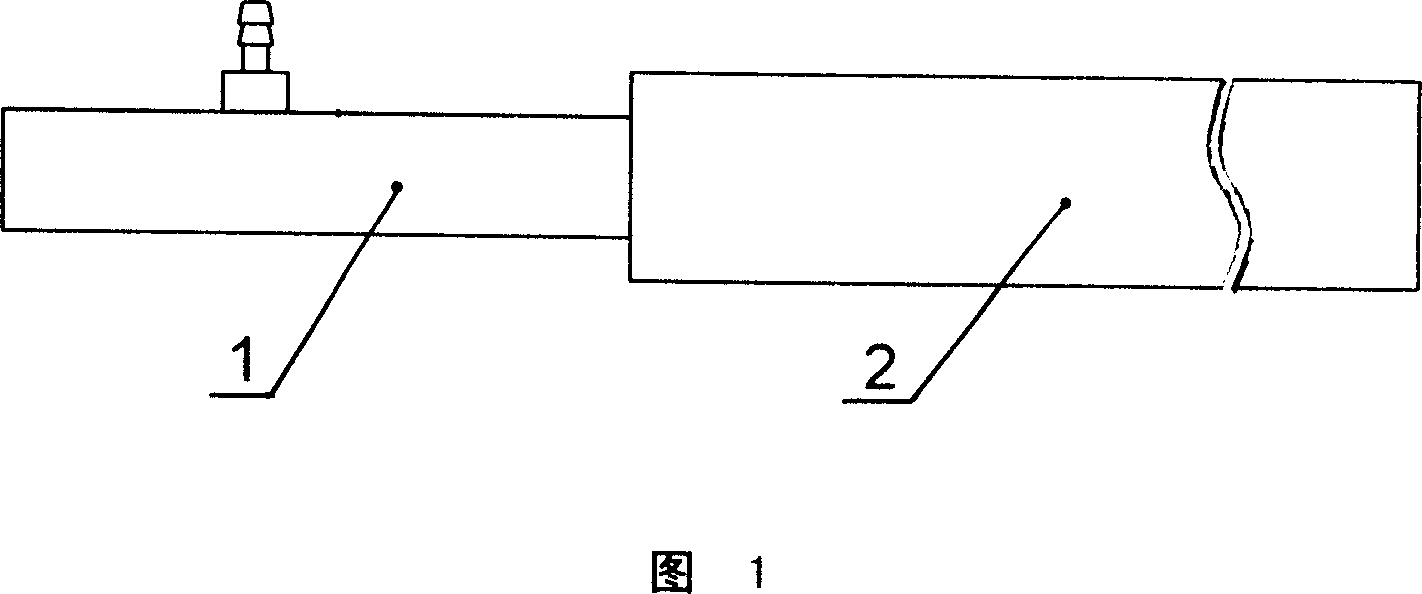
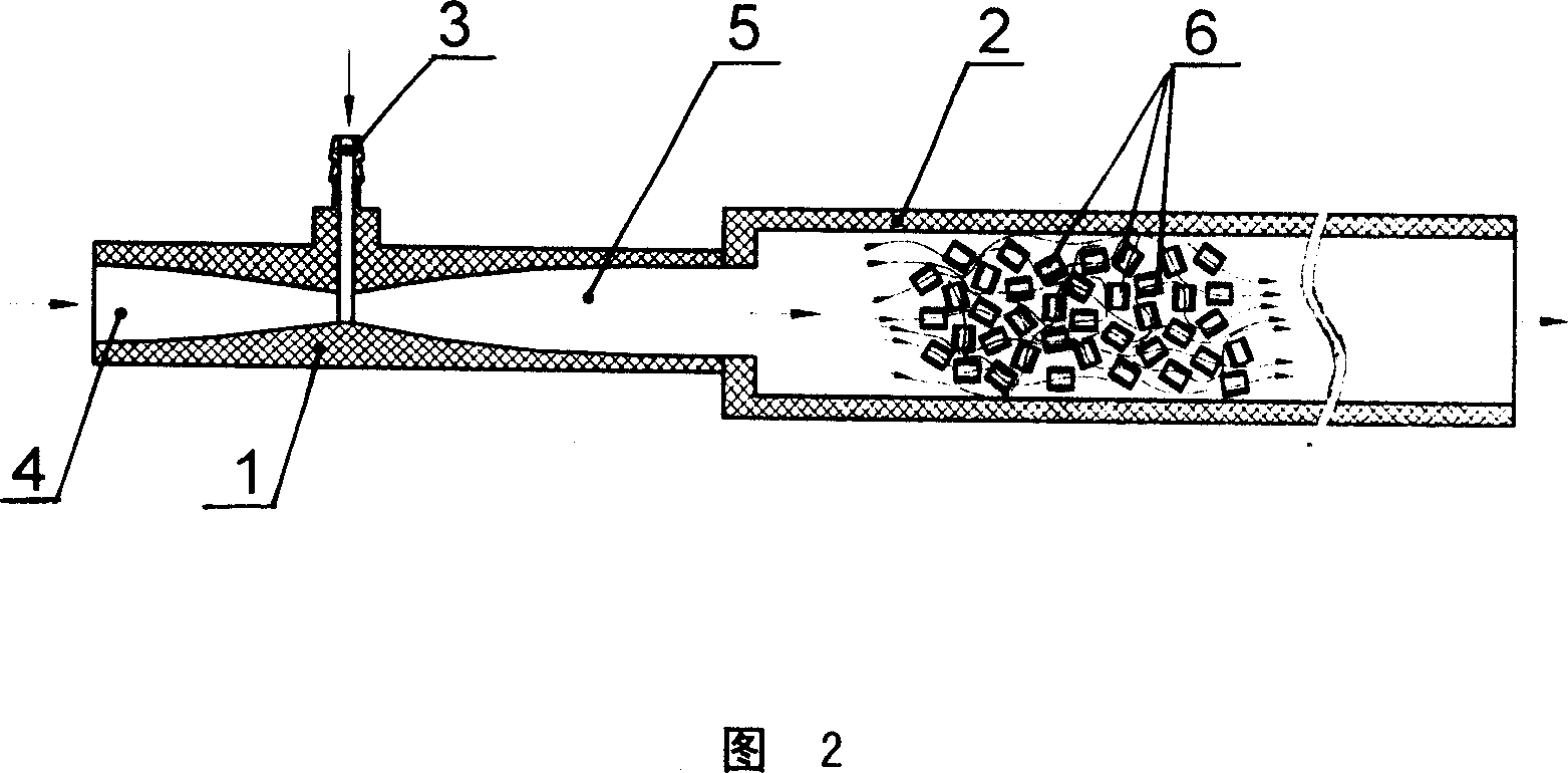
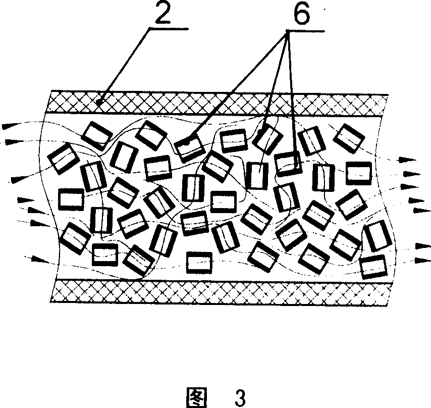
[0011] As shown in Figure 1-3, a gas-water turbulent flow remixing tube, it includes a Venturi jet tube 1, the Venturi jet tube 1 has a booster chamber 4, a negative pressure chamber 5 and an air inlet 3, the Venturi jet tube The pipe 1 is connected to the turbulent flow mixing pipe 2, and the turbulent flow mixing pipe 2 is filled with small and short pipe heads 6 in disorder.

[0012] As shown in Figure 2, when the water with a certain pressure and flow rate flows into the pressurized chamber 4 of the Venturi jet tube 1, a vortex effect is generated in the negative pressure chamber 5, and the air inlet on the Venturi jet tube 1 will be connected The gas in 3 is sucked into the negative pressure chamber 5 to form a gas-water vortex mixing phenomenon. Although it can play the role of air-water mixing, it has been proved that the air-...


PUM


Abstract

The gas-water turbulent flow remixing tube includes a Venturi jet tube with booster cavity, negative pressure cavity and gas inlet, and a turbulent flow remixing tube connected to the Venturi jet tube and with disorder filled fine stubs. The gas-water turbulent flow remixing tube has simple structure, low production cost, low running cost and high efficiency of mixing water and gas.

Description

1. Technical field [0001] The invention relates to a gas and liquid mixing device, in particular to a gas-water turbulent flow remixing tube. 2. Background technology [0002] In the prior art, Venturi jet tubes, micro-gap impeller mixing pumps, etc. are used when mixing gases in water bodies with a certain flow rate and pressure, each of which has its own advantages and disadvantages. Among them, the micro-gap impeller mixing pump grinds and stirs water and gas through a high-speed rotating impeller, so that the gas is fully mixed into the water body. The effect is very significant, and the mixing rate can reach 95-98%. However, the equipment is expensive and the operation cost is high. its application in the general field. However, the Venturi jet tube, which is widely used as a low-cost technology, has limited mixing effect and cannot meet the mixing requirements in some occasions. 3. Contents of the invention [0003] The object of the present invention is to provide...

Claims


Application Information

Patent Timeline
IPC IPC(8): B01F5/02B01F5/06B01F3/04
Inventor 朱鲁曰朱汉衡朱鲁铭
Owner 朱鲁曰
Why Eureka
Try Eureka