Resin control device of hot runner system for injection molding machine

A fluid cylinder and molding machine technology, applied in the field of resin quantity control, can solve the problems such as the inability to adjust the resin utilization time difference, the inability to perform fine control using the time difference, and the inability to precisely adjust the resin amount, etc., achieving simple structure, saving production costs, Easy work and effective

Inactive Publication Date: 2007-06-06
YUDO
View PDF0 Cites 1 Cited by
  • Summary
  • Abstract
  • Description
  • Claims
  • Application Information

AI Technical Summary

Problems solved by technology

Therefore, the control cannot be performed without a timer, and since the timer is used, the fine amount of resin cannot be adjusted by the time difference
[0003] As mentioned above, the conventional method of using a timer is a method of adjusting the amount of resin using a time difference, so there is a disadvantage that the correct amount of resin cannot be controlled, or there is a disadvantage that the manufacturing cost increases by using the timer
[0004] In addition, the existing method as mentioned above has a big problem such as the following: In order to adjust the injection amount of resin, it is necessary to ensure the technical ability of the timer. Relevant professionals, resulting in unnecessary waste of personnel costs
[0005] Moreover, the existing method using a timer as described above cannot precisely control the amount of resin due to the use of time differences.

Method used


Image

  • Resin control device of hot runner system for injection molding machine
  • Resin control device of hot runner system for injection molding machine
  • Resin control device of hot runner system for injection molding machine

Examples


Embodiment Construction

[0014] Hereinafter, the present invention will be described in detail based on the drawings.

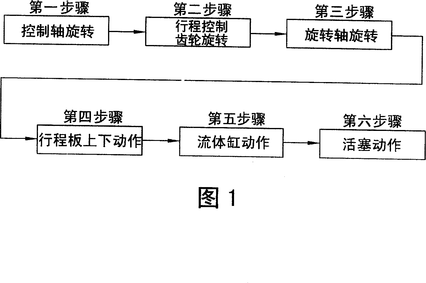
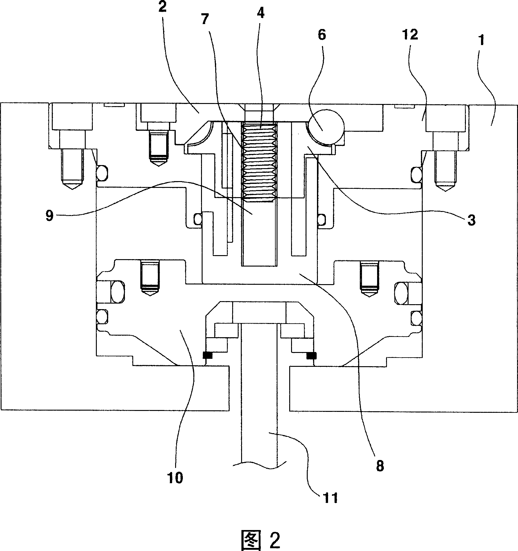
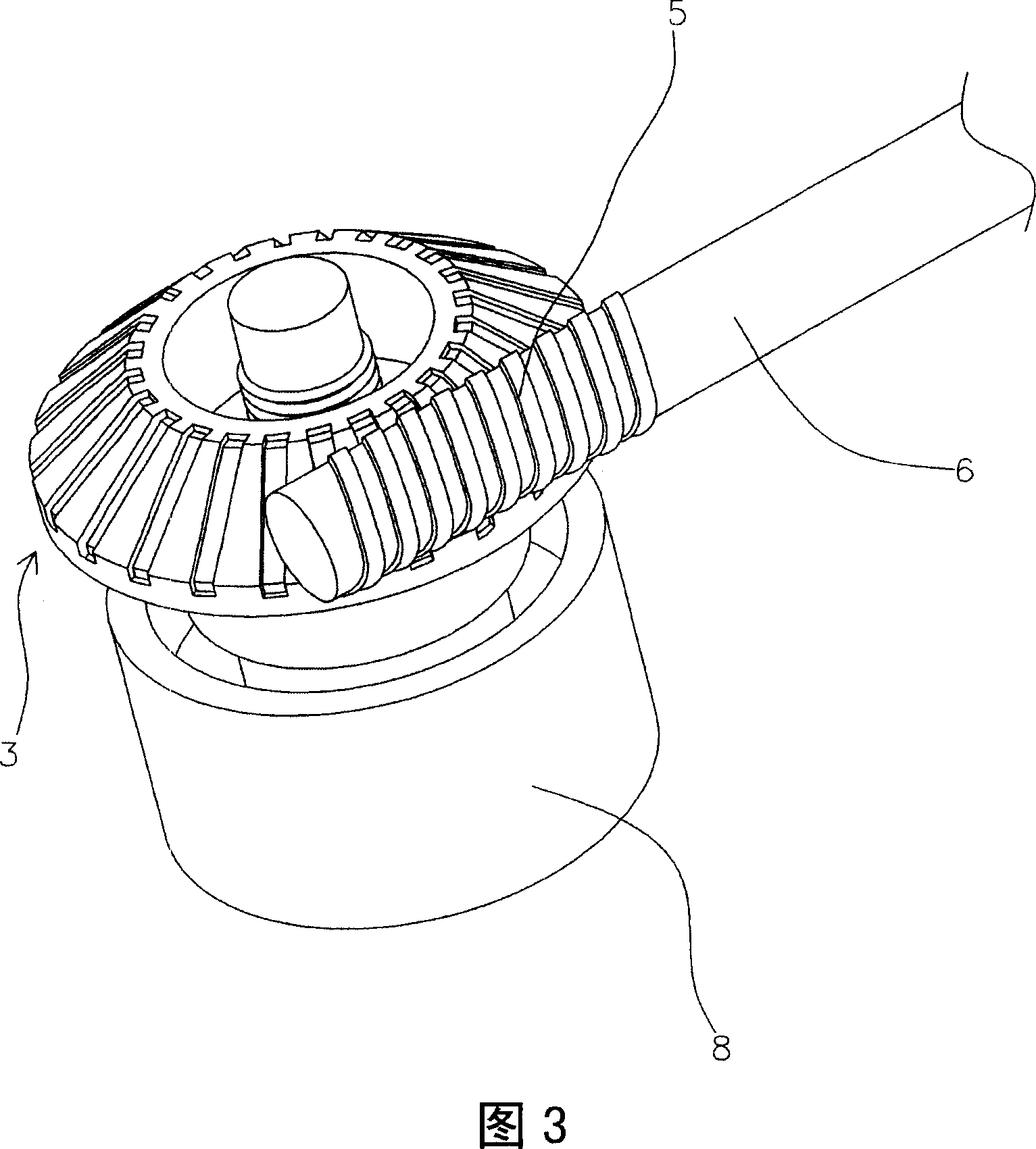
[0015] The present invention is a device in which, in a fluid cylinder for an injection molding machine that operates the fluid cylinder to adjust the amount of resin, the cylinder head 12 is fastened and fixed to the fixed plate 1, and the central part of the cylinder head 12 is fastened and connected to form a fluid cylinder. Cylinder cap 2 is fixed, and in the central part of cylinder cap 2, is provided with the rotating shaft 4 that fastens and connects stroke control gear 3, is formed with threaded part 9 at the lower end portion of rotating shaft 4, on one side of stroke control gear 3 , a control shaft 6 formed with a worm gear 5 is provided, the control shaft can be rotated by a motor or manually, and a stroke plate 8 formed with a threaded part 7 on the inside is provided at the lower end of the stroke control gear 3, so as to be connected with the rotation shaft 4 The threa...


PUM


Abstract

The present invention provides a method and apparatus for controlling the amount of resin only with machinery without extra calculator in cylinders of injection molding machines. In the cylinder of injection molding machine for adjusting the amount of resin with movement of cylinder, cylinder cover mounted to fixation plate. In the centre of the cylinder cap mounted to the center of a cylinder cover, a rotative shaft is coupled to the stroke control gear, with an externally threaded part formed at the lower part of the rotative shaft. A motor-operated or hand-operated control shaft having a worm gear (5) is placed at a side of the stroke control gear. The stroke plate having an internally threaded part is installed in the lower part of the stroke control to engage with threaded part formed on the rotative shaft so that the height of stroke plate is adjustable. Adjusting of up and down movement interval of valve pin by adjusting the up / down length of piston makes process to accurately adjust the flowrate of resin.

Description

technical field [0001] The present invention relates to a method and device for controlling the amount of resin in a fluid cylinder for an injection molding machine. In the fluid cylinder for an injection molding machine, the interval between valve pins capable of adjusting the amount of resin can be adjusted. A worm gear is installed on the rotating shaft that is manually rotated, and a stroke plate is installed on the upper side of the piston, so that the interval can be adjusted mechanically, so that no additional timer is needed, and the correct resin flow rate can be set only by the mechanical structure. Background technique [0002] Until now, a timer has been set in the fluid cylinder for injection molding machines to control the working time of the fluid cylinder, thereby controlling the outflow of resin. Therefore, control cannot be performed without a timer, and since the timer is used, a minute amount of resin cannot be adjusted by a time difference. [0003] As ...

Claims


Application Information

Patent Timeline
Patent Type & Authority Applications(China)
IPC IPC(8): B29C45/76
CPCB29C2045/2848B29C2045/2889B29C45/2806B29C45/281B29C45/76B29C45/18B29C45/23
Inventor 柳永熙
Owner YUDO
Why Eureka
Try Eureka