
High-pressure hydraulic diaphragm metering pump

A diaphragm type, metering pump technology, applied in the field of metering pumps, can solve the problems of shortening the life of three valves and diaphragms, wear, diaphragm damage, etc., to achieve convenient emptying and oil replenishment, simple operation procedures, and prolong service life Effect

Inactive Publication Date: 2007-06-06
杭州大潮泵业制造有限公司
View PDF0 Cites 12 Cited by
  • Summary
  • Abstract
  • Description
  • Claims
  • Application Information

AI Technical Summary

Problems solved by technology

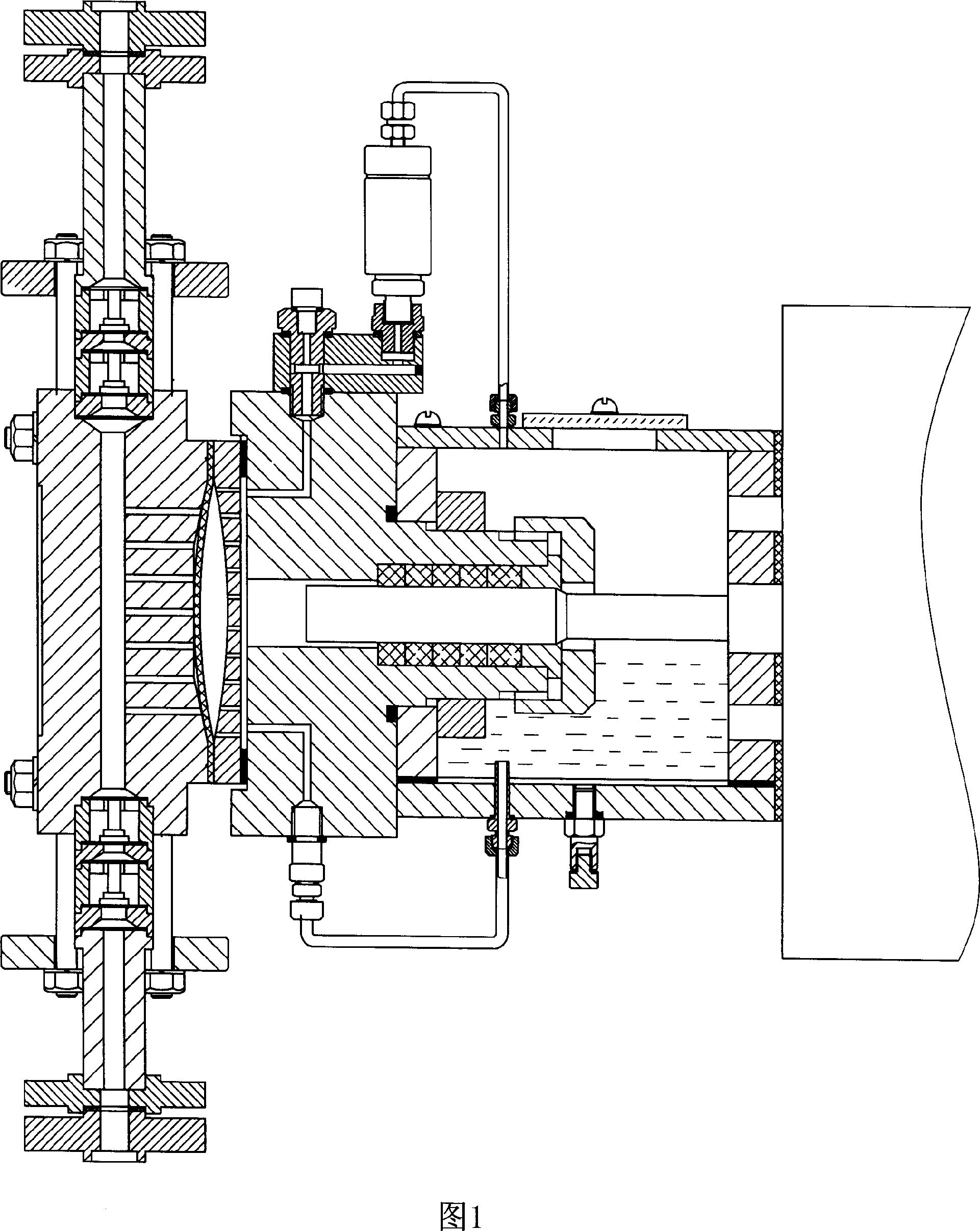
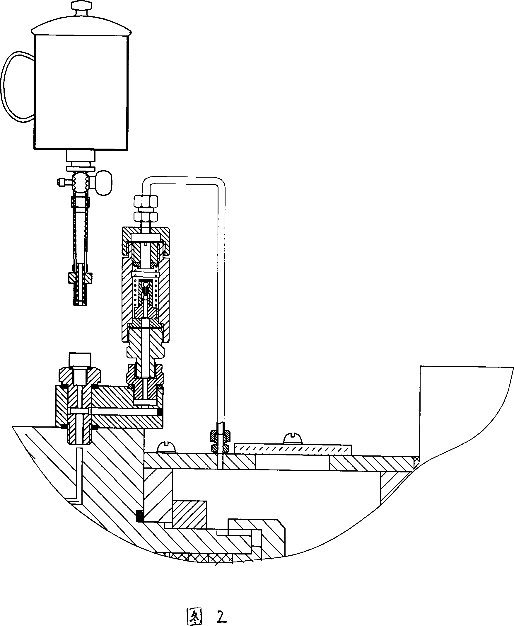
Its disadvantages are: the pressure relief valve, air release valve, and oil replenishment valve are set separately to increase the sealing leakage point, especially for the high-pressure hydraulic diaphragm pump, which is easy to cause instability of the hydraulic system and shorten the life of the three valves and the diaphragm; The oil inlet of the oil valve is directly connected to the bottom of the oil pool, and the dirty oil containing particles will be sucked into the hydraulic chamber, which may easily cause the sealing surface of the valve core (ball) of the pressure relief valve, air release valve, and oil replenishment valve to be poorly sealed, and even Wear and tear will cause the hydraulic internal circulation balance system to become unstable, which can cause the pressure not to go up and the diaphragm to be damaged in advance; the oil in the hydraulic chamber is special hydraulic oil, and the oil pool is connected to the chassis, resulting in the lubrication of the hydraulic chamber and the chassis. , high failure rate of hydraulic system
[0008] 3. The medium end of the pump head of the conventional hydraulic diaphragm metering pump is covered with small holes as the medium flow channel. There is a porous rear diaphragm plate between the cylinder body and the diaphragm. Under special circumstances such as a little excess oil, blockage of the liquid inlet or slow closing of the outlet one-way valve (this is a likely phenomenon), the diaphragm is easily damaged by the small hole on the pump head or the back of the pump under the action of high-pressure liquid. The small holes on the membrane plate are broken down and damaged, and even the rear membrane plate is broken by the diaphragm, and the failure is significantly improved. At the same time, due to the large number of sealing surfaces, it is easy to leak

Method used


Image

  • High-pressure hydraulic diaphragm metering pump
  • High-pressure hydraulic diaphragm metering pump
  • High-pressure hydraulic diaphragm metering pump

Examples


Embodiment Construction

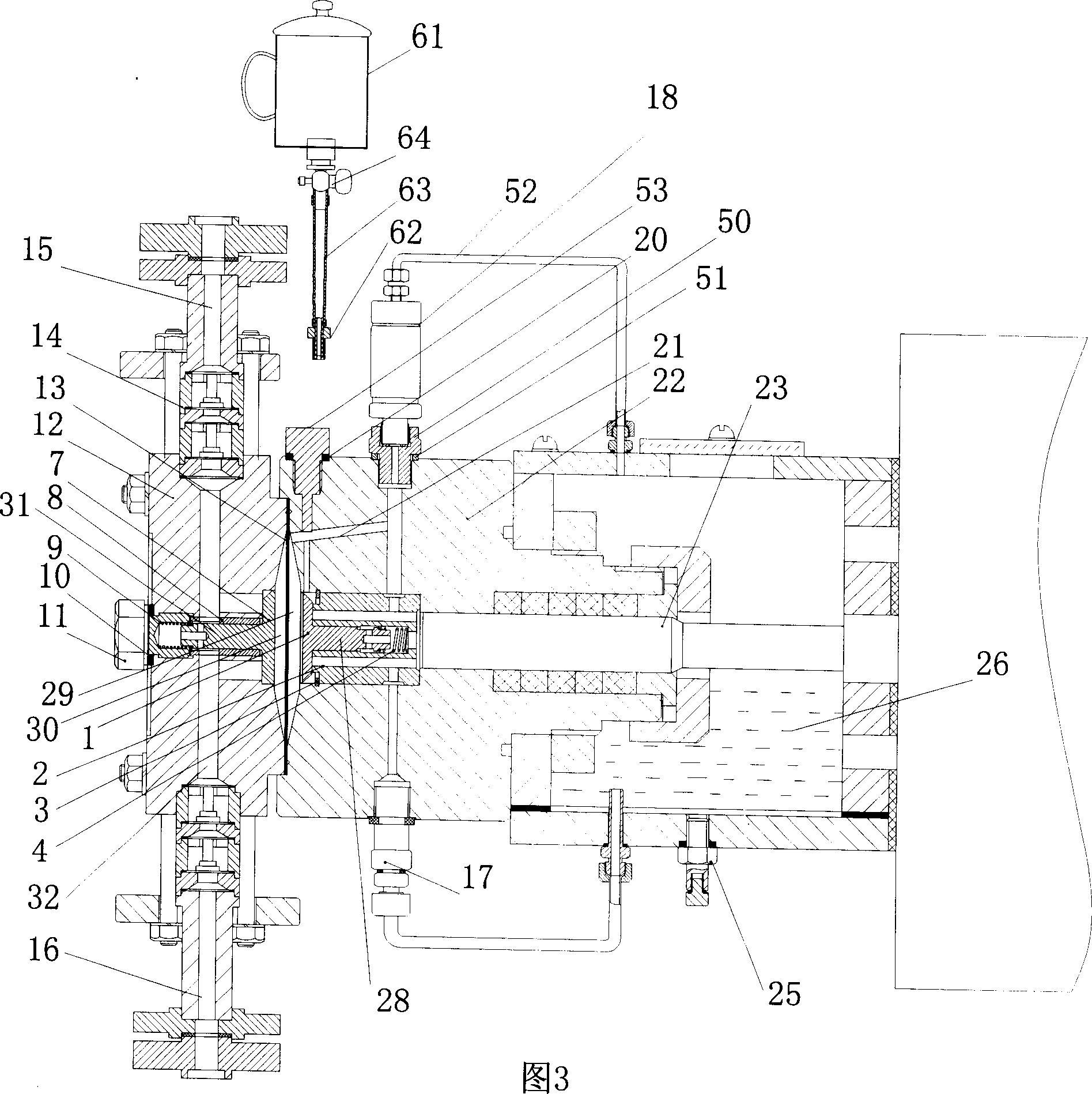
[0029] Referring to the accompanying drawings, the present invention will be described in detail below.

[0030] A high-pressure hydraulic diaphragm metering pump in the present invention includes an oil pool 26, a pump head 12, a diaphragm 13, a cylinder body 22, a plunger 23, and a one-way valve group 14, and also includes a rear-mounted diaphragm plate structure, The rear-mounted diaphragm structure is composed of a rear diaphragm 1, a spring 4 and a cylinder body 22. A hydraulic chamber 29 is formed between the cylinder body 22 and the diaphragm 13. Between the hydraulic chamber 29 and the plunger 23, there is a A guide rod through hole, the inner wall of the guide rod through hole is embedded with a bushing 2, the bushing 2 is fixed in the guide rod through hole of the cylinder body with a collar 3, a through hole is drilled in the center of the bush 2, and the guide rod 28 is movable In the through hole, the bushing 2 is also provided with four through holes connecting t...


PUM


Abstract

The present invention belongs to the field of metering pump technology, and is aimed at providing a high-pressure hydraulic diaphragm metering pump. Said metering pump includes oil tank, pump head, diaphragm, cylinder body, plunger and one-way valve unit. It also includes a rear-mounted diaphragm-protecting plate structure. The described rear-mounted diaphragm-protecting plate structure is formed from rear diaphragm-protecting plate, spring and cylinder body. Besides, it also includes an oil-supplementing structure and a front-mounted diaphragm-protecting structure. Said invention can greatly raise quality of metering pump.

Description

technical field [0001] The invention relates to the field of metering pumps, in particular to a high-pressure hydraulic diaphragm metering pump. Background technique [0002] Metering pumps are widely used in chemical industry, oil refining, pharmaceutical, electric power, paper making, food, urban water supply, industrial water, environmental protection and other occasions. Metering pump is a kind of positive displacement pump, which is divided into two categories: plunger pump and diaphragm pump. Diaphragm pump can be subdivided into hydraulic diaphragm pump and mechanical diaphragm pump. Hydraulic diaphragm pumps can be divided into metal diaphragm metering pumps and non-metallic diaphragm metering pumps due to different diaphragm materials. At present, the products used in domestic and foreign markets are mainly non-metallic diaphragm metering pumps, and the rated pressure is generally around 16MPa. The main features of the metering pump are accurate metering, high outp...

Claims


Application Information

Patent Timeline
Patent Type & Authority Applications(China)
IPC IPC(8): F04B43/067
Inventor 杨树东
Owner 杭州大潮泵业制造有限公司
Learn More