Grinding wheel constraining abrasive particle injection precise dressing processing method and device
A technology of finishing and grinding wheel grinding, which is applied in the field of material surface machining, can solve the problems of low processing efficiency, and achieve the effect of uncomplicated design, manufacture and installation
- Summary
- Abstract
- Description
- Claims
- Application Information
AI Technical Summary
Problems solved by technology
Method used
Image
Examples
Embodiment 1
[0029] The invention is carried out on an ordinary grinder M7120.
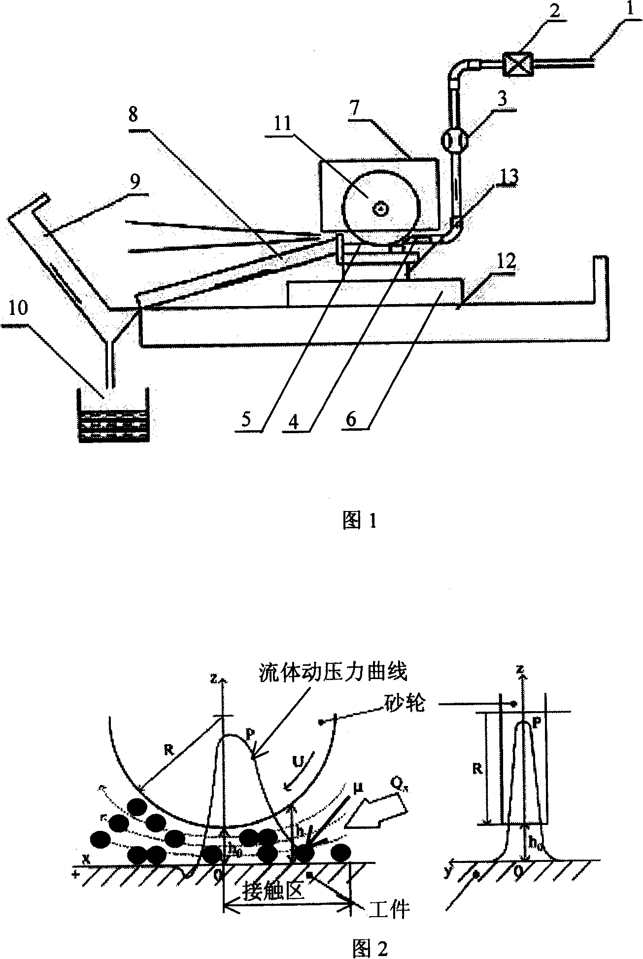
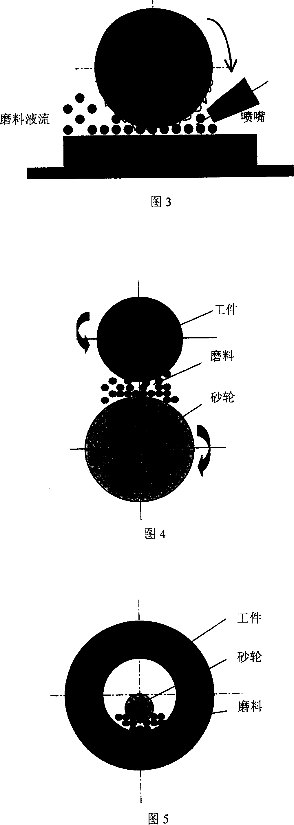
[0030] An abrasive injection system composed of an abrasive flow pressurized pump, an infusion pipe (1), a control valve (2), a flow meter (3) and a nozzle (4) is installed above the ordinary grinding machine. After the grinding wheel disc is installed, the A protective cover (7) is provided on the outer frame of the grinding wheel frame, and a liquid sump (8) and a liquid baffle (9) are installed on the direction that the workbench at the other end of the grinder faces the nozzle. After the workpiece is processed by the abrasive flow, it flows into the liquid storage tank (10) after passing through the liquid collecting tank and the baffle, and then is pumped out by the booster pump to enter a new round of spray finishing process, forming a closed cycle. The bottom of the liquid storage tank is preferably equipped with an electromagnet to prevent working iron filings from entering the circulation of the abras...
Embodiment 2
[0037] The invention is implemented on a cylindrical grinding machine.
[0038]Same as embodiment 1, at first be to install the grinding wheel constraint abrasive jet precision finish processing device, that is to add on the cylindrical grinding machine by the abrasive grain flow pressurized pump (1), control valve (2), flow meter (3), spray Abrasive jetting processing system composed of nozzle (4), protective cover (7), liquid sump (8), baffle plate (9) and liquid storage tank (10). Due to the structural characteristics of the cylindrical grinder, the direction and position of the abrasive flow nozzle will change.
[0039] When the processing workpiece (5) is fixed on the workbench (6), the emery wheel (11) is fixed on the emery wheel frame, and the grinding machine is started to grind the workpiece. When the workpiece surface roughness Ra<2 μm, stop the emery wheel feed. At this time, start the abrasive flow pressurizing pump, open the control valve, and carry out the grind...
Embodiment 3
[0045] Implementation of the present invention on an internal grinding machine
[0046] First add the abrasive flow pressurized pump (1), control valve (2), flow meter (3), abrasive flow nozzle (4), protective cover (7) to the internal grinding machine according to the method of embodiment 1 , a liquid collection tank (8), a fender (9) and a liquid storage tank (10) etc. constitute a grinding wheel restrained abrasive jet finishing system.
[0047] Then fix the grinding wheel disc and the Q235-A steel workpiece, start the grinding machine to grind the grinding wheel, and stop the feeding of the grinding wheel when the surface roughness of the workpiece reaches Ra=1.6-3.2 μm. Start the abrasive booster pump. Contains W50 (particle size 50-40μm) Al 2 o 3 Microparticle emulsion, Al 2 o 3 The weight percentage of the same emulsion is 2:100, through the control valve, the pressure is adjusted to 3×10 3 Pa is subjected to abrasive jet finishing. At this time, the relative pos...
PUM
| Property | Measurement | Unit |
|---|---|---|
| surface roughness | aaaaa | aaaaa |
| particle diameter | aaaaa | aaaaa |
| particle diameter | aaaaa | aaaaa |
Abstract
Description
Claims
Application Information
 - R&D
- Intellectual Property
- Life Sciences
- Materials
- Tech Scout
- Unparalleled Data Quality
- Higher Quality Content
- 60% Fewer Hallucinations
Browse by: Latest US Patents, China's latest patents, Technical Efficacy Thesaurus, Application Domain, Technology Topic, Popular Technical Reports.
© 2025 PatSnap. All rights reserved.Legal|Privacy policy|Modern Slavery Act Transparency Statement|Sitemap|About US| Contact US: help@patsnap.com


