Supercharge Your Innovation With Domain-Expert AI Agents!

Method for controlling AC motor

一种AC电机、电源的技术,应用在控制发电机、使用电/磁的方法的装置、控制机电制动器等方向,能够解决不能应用感应电机等问题

Active Publication Date: 2007-06-06
FUJI ELECTRIC CO LTD
View PDF2 Cites 10 Cited by
  • Summary
  • Abstract
  • Description
  • Claims
  • Application Information

AI Technical Summary

Problems solved by technology

Therefore, it can be applied to synchronous motors with permanent magnetic field, or induction motors with residual voltage, but it cannot be applied to induction motors with attenuated residual voltage

Method used


Image

  • Method for controlling AC motor
  • Method for controlling AC motor
  • Method for controlling AC motor

Examples


Embodiment Construction

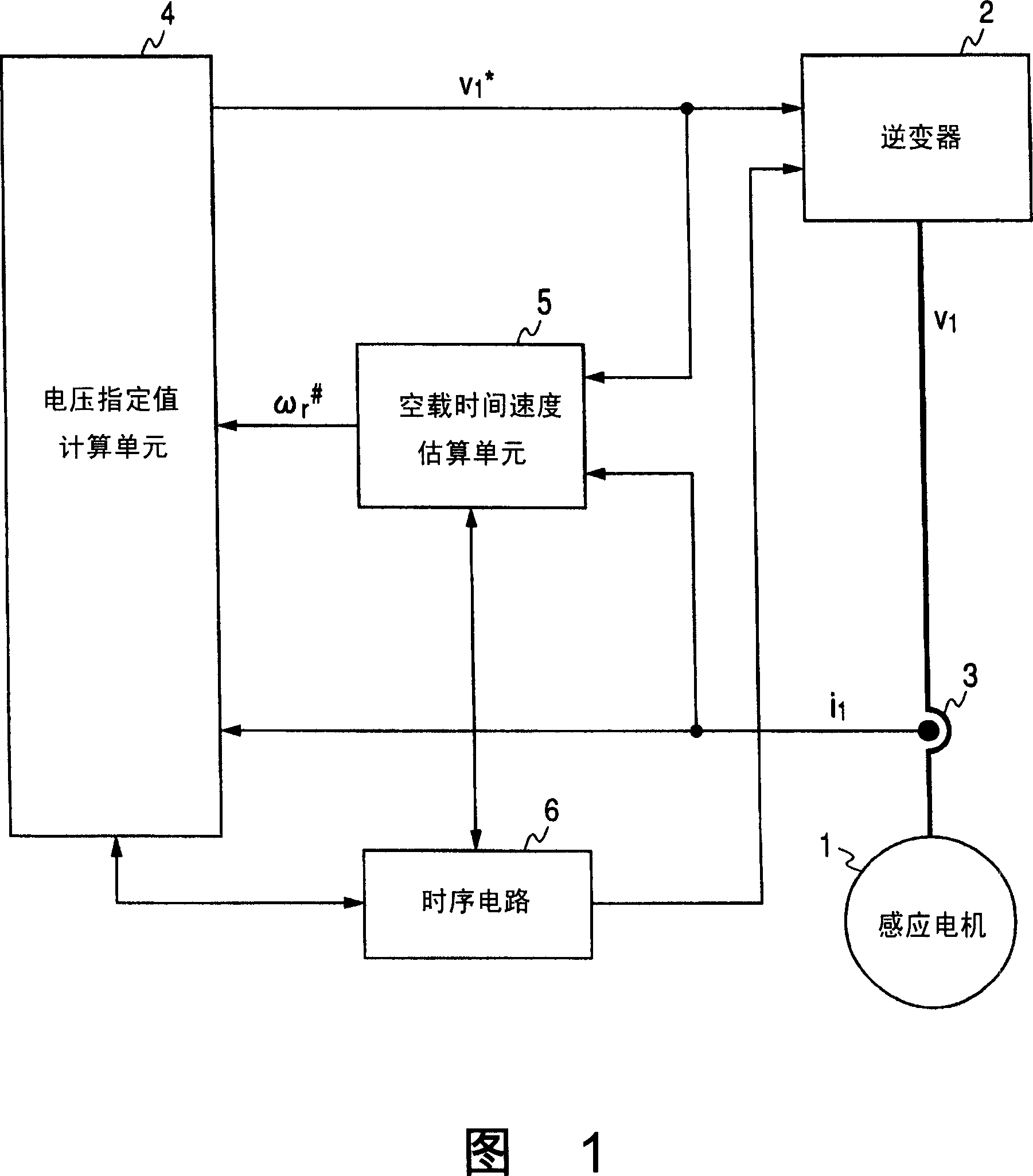
[0014] Fig. 1 is a circuit diagram showing an embodiment of the present invention. Reference numeral 1 indicates an induction motor as an AC motor, and 2 indicates that a desired primary voltage (v 1 ) of the inverter, 3 means to detect the primary current from the inverter 2 to the induction motor 1 (i 1 ) of the current detector, 4 means to generate a specified value of voltage (v 1 * ) in order to generate the above voltage v 1 The voltage designation value calculating unit of , 5 indicates calculating the estimated value of the rotation speed (ω r # ), and 6 denotes a sequential circuit that commands the operation of the inverter 2, the voltage designation value calculation unit 4, the dead time estimation unit 5, and the like.

[0015] As a normal operation of the induction motor 1 based on the sequence signal from the sequential circuit 6, the voltage designation value calculation unit 4 takes the primary angular frequency designation value (ω 1 ) and by pairing ω ...


PUM


Abstract

An inverter that supplies a desired primary voltage (v1) to an induction motor, a current detector that detects a primary current (i1) from the inverter to the induction motor, a voltage command value calculating unit that generates a voltage command value (v1*) for generating the voltage v1, an idle-time speed estimating unit that calculates an estimated value (omega r<#> ) of the rotary speed when the induction motor is idling, and a sequence circuit that commands the operations of these units are provided. The idle-time speed estimating unit switches a method for deriving the estimated value on the basis of a current value in the case where a short circuit is generated between windings when the induction motor is idling.

Description

technical field [0001] The present invention relates to a method for controlling an AC motor in which variable speed control of the AC motor is performed while power is supplied to the AC motor from a variable voltage variable frequency inverter, and more particularly to a method for deriving an estimated value of rotational speed when the motor is unloaded method. Background technique [0002] Recently, the methods disclosed in Japanese Patent No. 3,636,340 and JP-A-11-346500 have become known methods for use in variable-voltage variable-frequency inverters (hereinafter simply referred to as inverters) for driving AC motors. When the AC motor is stopped and restarted with no load, for example, the AC motor is controlled when restarting after recovering from a momentary service interruption of a commercial power supply as an inverter input power source. [0003] In a control method in which at least one of the semiconductor switching devices constituting the main circuit is...

Claims


Application Information

Patent Timeline
Patent Type & Authority Applications(China)
IPC IPC(8): H02P21/00H02P21/02H02P21/14H02P27/00H02P27/02H02P27/06H02P1/30H02P21/18H02P21/24H02P21/34H02P23/07H02P23/14
CPCH02P1/029G01P3/44H02P3/22
Inventor 田岛宏一八须康明
Owner FUJI ELECTRIC CO LTD
Features
  • R&D
  • Intellectual Property
  • Life Sciences
  • Materials
  • Tech Scout
  • Unparalleled Data Quality
  • Higher Quality Content
  • 60% Fewer Hallucinations
Learn More