Non-linear ultrasonic diagnostic imaging using intermodulation component signals

A technology for ultrasonic diagnosis and intermodulation components, which is applied in the field of medical diagnostic imaging systems and can solve problems such as attenuation, reduction of image diagnosis quality, and reduction of echo signal-to-noise ratio characteristics.

Inactive Publication Date: 2007-06-06
KONINKLIJKE PHILIPS ELECTRONICS NV
View PDF2 Cites 15 Cited by
  • Summary
  • Abstract
  • Description
  • Claims
  • Application Information

AI Technical Summary

Problems solved by technology

As shown in the examples in the '075 patent, intermodulation products are typically in the center of the passband or higher, and thus can be subject to substantial attenuation in deeper depth imaging
This attenuation may reduce the signal-to-noise ratio characteristics of the received echoes and thus reduce the diagnostic quality of these images

Method used


Image

  • Non-linear ultrasonic diagnostic imaging using intermodulation component signals
  • Non-linear ultrasonic diagnostic imaging using intermodulation component signals
  • Non-linear ultrasonic diagnostic imaging using intermodulation component signals

Examples


Embodiment Construction

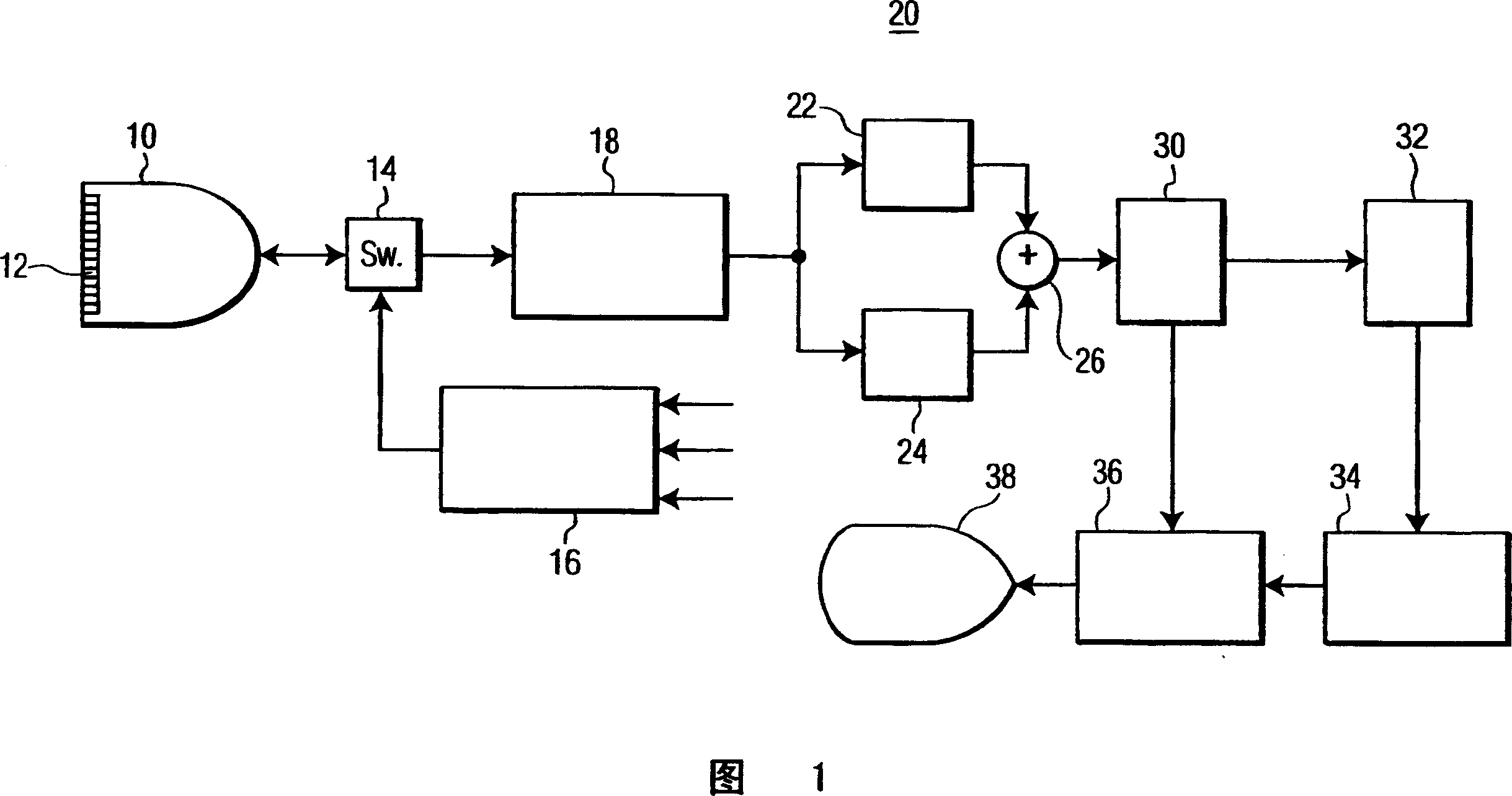
[0013] Referring first to Figure 1, there is shown an ultrasonic diagnostic imaging system constructed in accordance with the principles of the present invention. The ultrasound system of FIG. 1 utilizes a transmitter 16 that transmits a multi-frequency beam to non-linearly generate a difference frequency signal within the subject to be imaged. The transmitter is coupled to elements of the array transducer 12 of the scan head 10 via a transmit / receive switch 14 . As shown, the transmitter responds to a number of control parameters that determine the characteristics of the transmitted beam. Two main frequencies f of the multi-frequency beam 1 and f 2 controlled, the two frequencies determine the difference (f 1 -f 2 ) The frequency at which the frequency component is located. The amplitudes and intensities a and b of these two transmitted frequency components are also controlled such that the transmitted beamforming (bsin(2πf 1 t)+asin(2πf 2 t)) form. The received diffe...


PUM


Abstract

An ultrasonic imaging system transmits waveforms containing first and second major frequency components which are intermodulated by passage through a nonlinear medium or interaction with a contrast agent microbubble to produce a difference frequency component. In an illustrated embodiment the second major frequency is twice the frequency of the first major frequency, resulting in a difference frequency signal at the first major frequency. Two differently modulated transmit waveforms are transmitted and the difference frequency component is separated by pulse inversion.

Description

technical field [0001] The present invention relates to medical diagnostic imaging systems, and more particularly, to ultrasonic diagnostic imaging systems in which imaging is performed using non-linear intermodulation products of transmitted signals. Background technique [0002] Imaging with nonlinear signals finds two main applications in diagnostic ultrasound today. One is tissue harmonic imaging, in which a linear (usually sinusoidal) waveform is allowed to experience natural distortion as it is sent through the body. This distortion causes the occurrence of non-linear harmonic components, the most important part of which is usually in the second harmonic of the fundamental transmit frequency. The received echoes are filtered to separate nonlinear components from linear components. A preferred separation technique is known as pulse inversion and is described in US Pat. No. 5,951,478 (Hwang et al.). Images generated from non-linear components are required due to the l...

Claims


Application Information

Patent Timeline
Patent Type & Authority Applications(China)
IPC IPC(8): A61B8/00A61B8/14
CPCA61B8/14G01S7/52038A61B8/00A61B8/481G01S15/8952G01S15/8963
Inventor M·阿弗基欧S·詹森
Owner KONINKLIJKE PHILIPS ELECTRONICS NV
Why Eureka
Try Eureka