Air bath with bypass vent

A technology of air bath and air vent, applied in the field of air transmission system, to achieve the effect of excellent bathing experience

Inactive Publication Date: 2007-06-06
KOHLER CO
View PDF8 Cites 2 Cited by
  • Summary
  • Abstract
  • Description
  • Claims
  • Application Information

AI Technical Summary

Problems solved by technology

As such, the ability to provide soft, low density foam is somewhat limited without the use of auxiliary tanks or accumulators, as described in U.S. Patent 4,907,305

Method used


Image

  • Air bath with bypass vent
  • Air bath with bypass vent
  • Air bath with bypass vent

Examples


Embodiment Construction

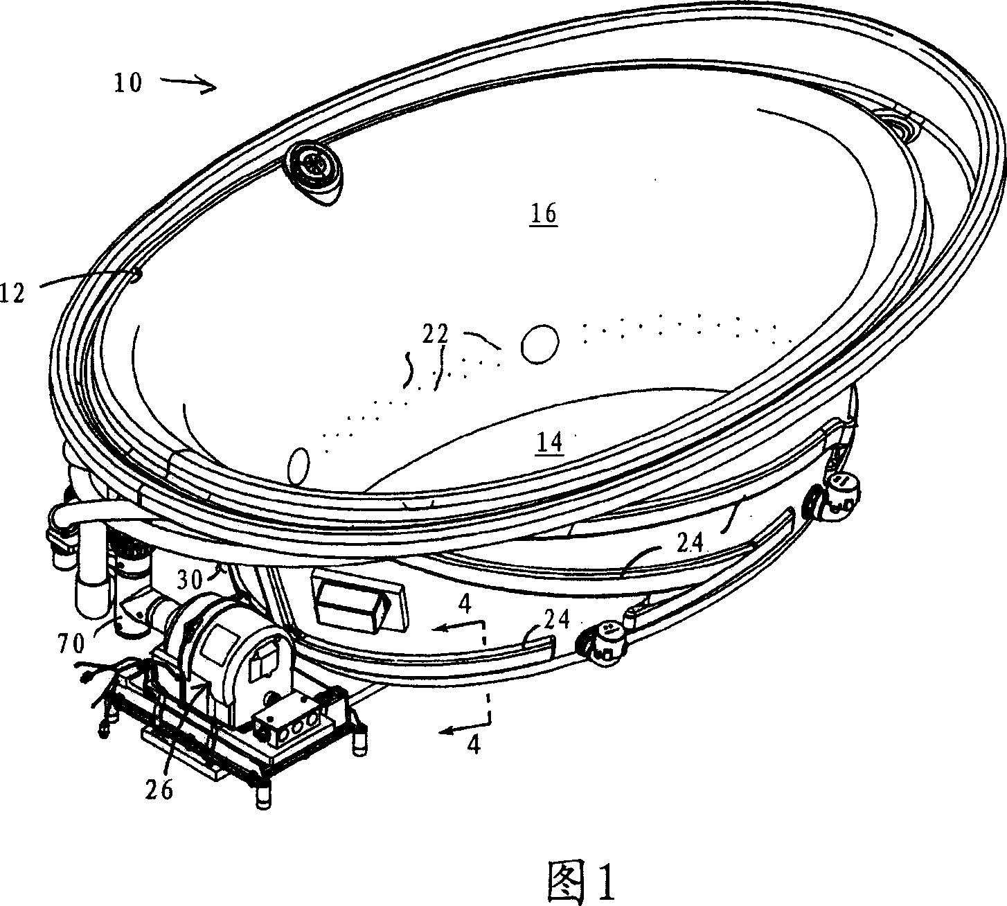
[0027] Referring to FIG. 1 , an air bath 10 has a basin 12 defining a bottom 14 and shaped vertical side walls 16 . The bottom 14 has a drain opening with a drain plug preferably indirectly controlled by an actuator with a flow-through part. It should be noted that while shown and described as a bath, the air bath 10 may take other forms, such as a spa or swimming pool.

[0028] The side wall 16 of the pool 12 is formed with a plurality of openings defining an air outlet 22 , preferably in the lower half of the side wall 16 . The air outlet 22 is a simple circular hole extending through the thickness of the side wall 16 . The air outlets 22 are preferably sized and arranged in a pattern designed to provide improved air flow for full-body air infusion spas, as in commonly owned and co-pending U.S. Disclosed in patent application Ser. No. 10 / 774,123.

[0029] Briefly, the air outlets 22 are arranged in a plurality of lateral (or horizontal) rows, three of which are shown in F...


PUM


Abstract

An air bath has air outlets extending around the side walls of the water basin. Air is delivered to the air outlets through a ring-like air manifold coupled to a blower by conduit. The conduit has a bypass vent that siphons off a portion of the air flow otherwise passing to the air outlets and maintains the blower in communication with ambient air. The air delivery system provides a wider range of bubble densities by allowing the blower to operate at lower speeds without overheating or stalling from back pressure arising from the pressure head of the water in the basin.

Description

technical field [0001] The present invention relates to a bathtub in which air is bubbled through the water, and more particularly, the present invention relates to an air delivery system for such a bathtub. Background technique [0002] Therapeutic baths and pools are well known. Mineral spas or whirlpool thermal baths are common examples, where water flows from spouts leading into the pool wall into water below the surface, usually towards muscular areas of the body such as the shoulders, back or thighs. The force from each jet directly "massages" the bather and agitates the water to provide a therapeutic effect to other parts of the body not directly in the flow path of said jets. US Patent 6,185,757 discloses one such bath with water jets. [0003] Some tubs instead use airflow to agitate the water. US Patents 5,898,958 and 6,317,903 both disclose a bath that introduces air into the water by passing air from a blower or pump through conduits and manifolds to air jets ...

Claims


Application Information

Patent Timeline
Patent Type & Authority Applications(China)
IPC IPC(8): A61H33/02A61H33/06
CPCA61H2033/023A61H33/6026A61N2005/0663A61H2033/0083A61H33/02A61H2033/0058A61H2201/10A61H33/60
Inventor 彼得·W·斯瓦特罗纳德·鲍尔黛安娜·Q·王
Owner KOHLER CO
Why Eureka
Try Eureka