Device and method for treating filament yarn and fancy knotted, migrated, and false-twist yarn

A filament yarn and yarn technology, applied in the field of snowflake yarn and false twisted yarn

Active Publication Date: 2007-06-06
HEBERLEIN & CO AG
View PDF6 Cites 7 Cited by
  • Summary
  • Abstract
  • Description
  • Claims
  • Application Information

AI Technical Summary

Problems solved by technology

In the case of double or multiple nozzles, both the nozzle body and the cover must be used double or multiple, which is a disadvantage compared to a narrow distance of the yarn flow path

Method used


Image

  • Device and method for treating filament yarn and fancy knotted, migrated, and false-twist yarn
  • Device and method for treating filament yarn and fancy knotted, migrated, and false-twist yarn
  • Device and method for treating filament yarn and fancy knotted, migrated, and false-twist yarn

Examples


Embodiment Construction

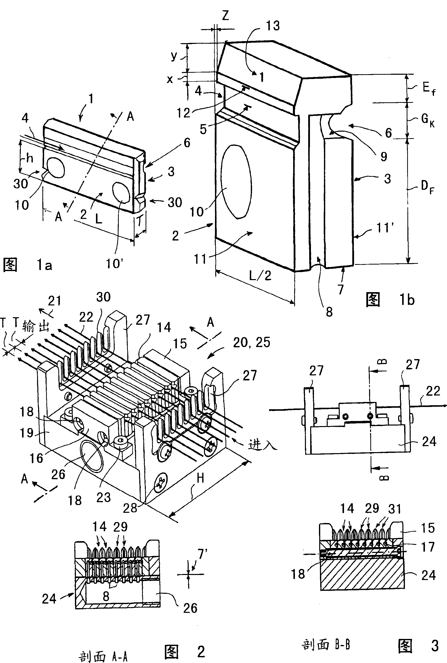
[0061]FIGS. 1 and 1 a show a spinneret / cover plate 1 , which is at the same time a cover plate and a spinneret plate, with a corresponding half of the yarn channel 17 . The front side shows the cover plate side 2 and the back side shows the spinneret side 3 , each having one half of the yarn channel 17 . On the front side 2 half 4 of the yarn channel enters the spinneret / cover plate 1 with the deflector 5 . On the back side of the spinneret side is half of the yarn channel 6 . An air supply channel 8 can be seen in section in FIGS. 1a and 2 (below). The air inlet channel 8 is introduced with a transverse hole 9 into the half 6 of the yarn channel with the spinneret 7 . The spinneret / cover plate 1 has two through holes 10 and 10' for the clamping plate 1. As can be seen from FIG. 3 , each two spinneret / cover plates 1 are in close contact with each other end-to-end. The corresponding sealing surface part 11 is designated by the dimension parameters h and L, wherein L is simu...


PUM


Abstract

The invention relates to a device for treating filament yarn by means of air nozzles comprising at least two injector / cover plates that can be clamped together, and at least one air supply channel. Said injector / cover plates form a yarn treatment chamber in the assembled state. According to the invention, the yarn treatment chamber is formed between the injector / cover plates that can be clamped together, in the longitudinal direction of the plates, and the air nozzle is embodied as an open nozzle comprising a threading slit and an individual air supply channel for the yarn channel in the injector / cover plates. The invention has two decisive advantages. The shape of the injector / cover plates is limited to the inherent core functions, namely a yarn channel formed in the plates, the threading slit, and the individual air supply channel for the yarn channel in the plate. The miniaturisation of the injector / cover plates significantly simplifies the production problems.

Description

technical field [0001] The invention relates to a device for processing filament yarns by means of a nozzle with a yarn channel, which is designed as an open and separate nozzle with a yarn guide groove and a medium feed channel into the yarn channel; and a A method of processing filament yarns by means of a nozzle with a yarn channel, which is designed as a separate open nozzle with a free yarn guide groove and a medium feed channel into the yarn channel. The invention also relates to a snowflake yarn, a swimming yarn and a false twist yarn. Background technique [0002] Filament yarns are air treated in the spinning process after the spinning process in order to improve the joining of the individual filament yarns for yarn processing. There are two different roles here: [0003] - for the manufacture of migratory yarns and [0004] - Eddy current for making snowflake yarn. [0005] The purpose of eddy currents is primarily to improve the engagement, but also to improve...

Claims


Application Information

Patent Timeline
Patent Type & Authority Applications(China)
IPC IPC(8): D02J1/08D02G1/16D02G1/04
CPCD02J1/08D02G1/04D02G1/161D02G1/16
Inventor P·布奇穆勒
Owner HEBERLEIN & CO AG
Why Eureka
Try Eureka