
Nonlinear ultrasonic diagnostic imaging using intermodulation product signals

An intermodulation component and non-linear technology, applied in the field of medical diagnostic imaging systems, can solve problems such as reducing image diagnostic quality and reducing echo signal-to-noise characteristics

Inactive Publication Date: 2007-06-06
KONINKLIJKE PHILIPS ELECTRONICS NV
View PDF2 Cites 13 Cited by
  • Summary
  • Abstract
  • Description
  • Claims
  • Application Information

AI Technical Summary

Problems solved by technology

This attenuation reduces the signal-to-noise characteristics of the received echoes and thus reduces the diagnostic quality of the image

Method used


Image

  • Nonlinear ultrasonic diagnostic imaging using intermodulation product signals
  • Nonlinear ultrasonic diagnostic imaging using intermodulation product signals
  • Nonlinear ultrasonic diagnostic imaging using intermodulation product signals

Examples


Embodiment Construction

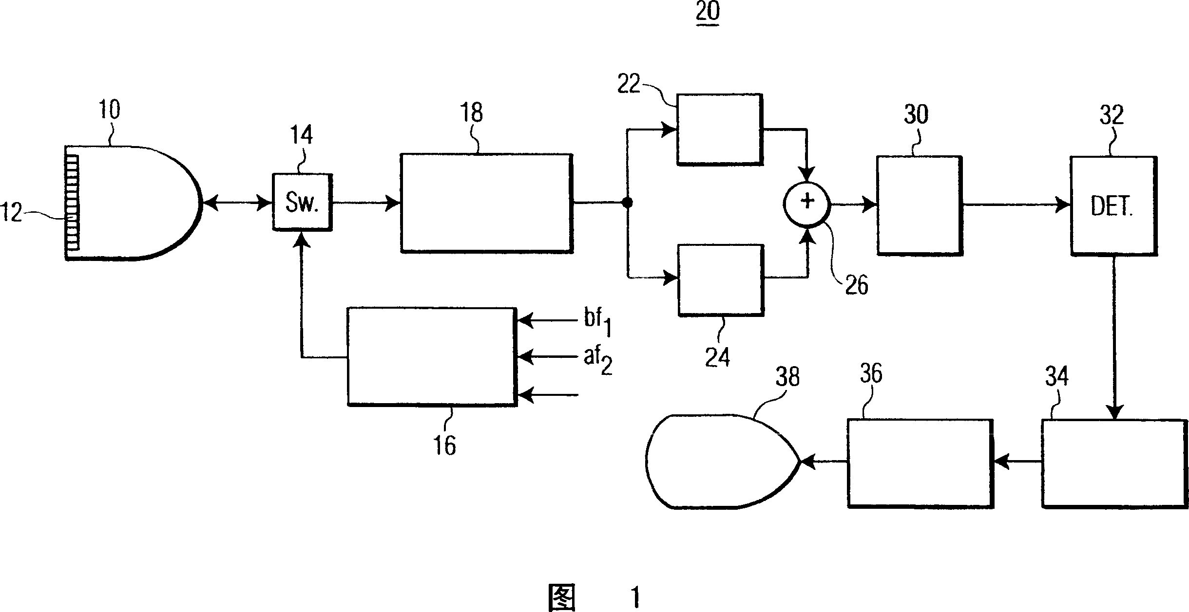
[0013] Referring first to Figure 1, there is shown an ultrasonic diagnostic imaging system constructed in accordance with the principles of the present invention. The ultrasound system of FIG. 1 utilizes a transmitter 16 that transmits a multi-frequency beam for non-linear generation of a difference frequency signal within an object to be imaged. The transmitter is coupled to elements of the array transducer 12 of the scan head 10 through a transmit / receive switch 14 . The transmitter responds to a number of control parameters that determine the characteristics of the transmit beam, as shown. Controlling the two main frequencies f of the multi-frequency beam 1 and f 2 , the two frequencies determine the difference (f 1 -f 2 ) The frequency at which the frequency component is located. Also controlled are the amplitudes or intensities a and b of the two transmit frequency components such that the transmit beam has (bsin(2πf 1 t)+asin(2πf 2 t)) form. However, as a differe...


PUM


Abstract

An ultrasonic imaging system transmits waveforms containing first and second major frequency components which are intermodulated by passage through a nonlinear medium or interaction with a contrast agent microbubble to produce a difference frequency component. In an illustrated embodiment the transmit waveforms are square waves exhibiting only odd harmonic components. The first and third harmonic components are intermodulated by nonlinear effects to produce a difference frequency signal at the second harmonic frequency.

Description

technical field [0001] The present invention relates to medical diagnostic imaging systems, and more particularly to ultrasonic diagnostic imaging systems in which nonlinear intermodulation products of transmitted signals are used for imaging. Background technique [0002] Currently, imaging using nonlinear signals has two main uses in diagnostic ultrasound. One use is tissue harmonic imaging, where a linear (typically sinusoidal) waveform is transmitted through the body to allow it to undergo natural distortion during imaging. This distortion causes the appearance of non-linear harmonic components, the most significant of which is usually located at the second harmonic of the fundamental transmit frequency. Filters the received echo, thereby separating nonlinear components from linear components. A preferred separation technique is called pulse inversion, as described in US Patent 5,951,478 (Hwang et al.). This image is desired due to multipath scattering, which produces...

Claims


Application Information

Patent Timeline
Patent Type & Authority Applications(China)
IPC IPC(8): G01S15/89G01S7/52A61B8/00A61B8/14
CPCG01S7/52038A61B8/481G01S7/5202G01S15/8952G01S15/8963A61B8/14G01S15/89G01S7/52
Inventor S·詹森M·阿弗基欧
Owner KONINKLIJKE PHILIPS ELECTRONICS NV
Learn More