Centrifugal switch of split-phase motor

A centrifugal switch and phase-splitting technology, which is applied to electric switches, starters of single-phase induction motors, motor generators/starters, etc., can solve problems such as increasing noise, increasing intervals, and accelerating wear of contact parts , to reduce wear and reduce noise

Inactive Publication Date: 2007-06-13
LG ELECTRONICS (TIANJIN) APPLIANCES CO LTD
View PDF0 Cites 3 Cited by
  • Summary
  • Abstract
  • Description
  • Claims
  • Application Information

AI Technical Summary

Problems solved by technology

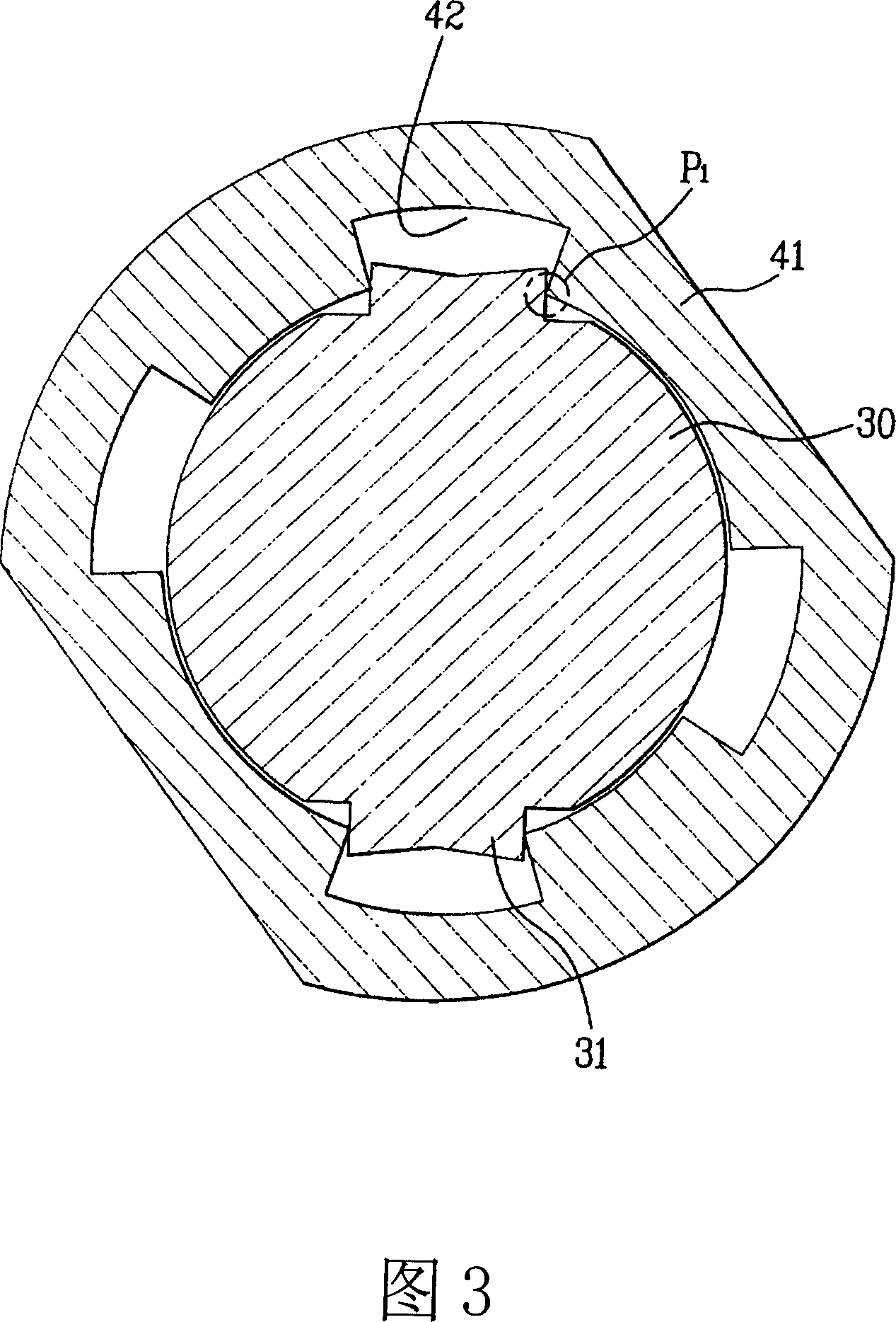
[0008] 1. Since the limiter of the above-mentioned shaft and the card groove of the sleeve are in the state of line contact (P1 part), the wear of the above-mentioned contact part will be accelerated during the long-term driving of the above-mentioned split-phase motor
[0009] 2. With the wear generated in the above-mentioned contact portion, the interval between the rotation direction of the above-mentioned shaft and the sleeve will become larger, resulting in increased noise caused by mutual interference in the above-mentioned shaft and sleeve. The above-mentioned noise is at the beginning of the motor Will be larger when driving and when ending driving

Method used


Image

  • Centrifugal switch of split-phase motor
  • Centrifugal switch of split-phase motor
  • Centrifugal switch of split-phase motor

Examples


Embodiment Construction

[0030] Referring to accompanying drawing 4 below, the centrifugal switch of the split-phase motor in the present invention is described.

[0031] As shown in Figure 4, the above-mentioned centrifugal switch 200 includes: a sleeve 210, which is inserted into the limiter 110 of the shaft 100, and a flange portion 213 is formed on its outer peripheral surface; The outside of the cylinder 210 is movably inserted along the axial direction of the above-mentioned sleeve 210, and when it reaches a predetermined position, the circuit of the auxiliary coil 12 is disconnected; the centrifugal actuator 230 is formed with at least two or more, and in When the shaft 100 rotates, it is opened outward by the centrifugal force generated; the tension spring 240 generates an elastic restoring force in the direction of converging on the centrifugal actuator 230 .

[0032] At this time, as shown in FIG. 5 , the inner surface of the sleeve 210 is formed with a locking groove 211 , and the locking g...


PUM


Abstract

A kind of centrifugal switch of split-phase motor, includes: sleeve, it is inserted into the limitative units of axis, and forms a flange part over its outer circumference; sliding block, it lies in the outer side of above-said sleeve, and is inserted movably along the axis direction of above-said sleeve, and then disconnect the assistant coil circuit when it arrives in the given position; the centrifugal actuator, it must be 2 pieces at least or more, and opens outwards under the centrifugal force it produces when the above-said axis rotates; stretch spring, it will produce elastic resilience along the direction in which it converges the above-side centrifugal actuator, and a groove is formed inside of the sleeve, the groove contacts with the two sides of the above-said limitative units in the rotary direction. The invention will reduce maximally the wear and tear of the contacting position where it is produced by axis and centrifugal switch, and reduce the noise also.

Description

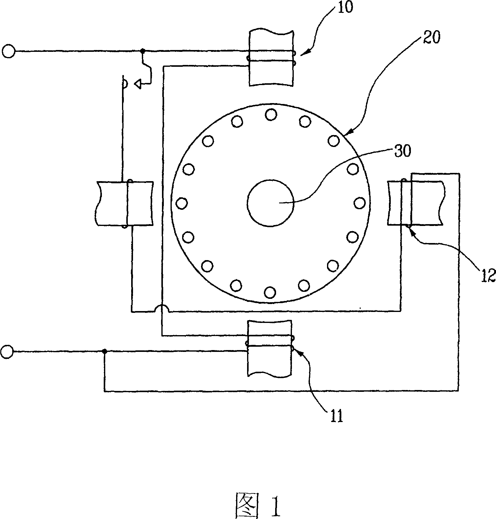
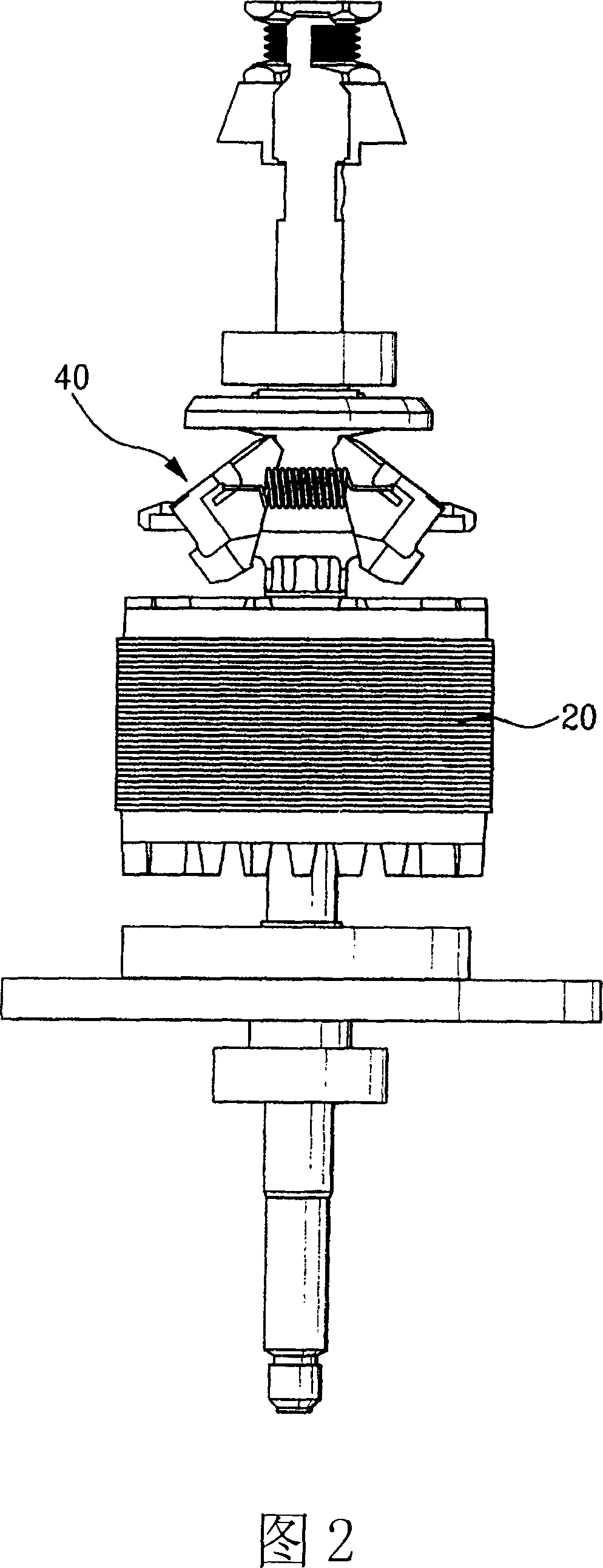
technical field [0001] The invention relates to a centrifugal switch of a split-phase motor. Background technique [0002] Generally speaking, centrifugal switches are used in home appliances such as dryers, and the centrifugal switches are also used in devices such as split-phase motors, in which a main coil 11 and an auxiliary coil 12 are wound. [0003] Next, the centrifugal switch of the above-mentioned split-phase motor will be described with reference to FIG. 1 and FIG. 2 . [0004] The split-phase motor includes: a stator 10 wound with a main coil 11 and an auxiliary coil 12; a rotor 20 rotated by the stator; a shaft 30 combined with the rotor 20; a centrifugal motor inserted into the shaft 30. Switch 40. [0005] As shown in FIG. 3 , a stopper 31 is formed on the outer peripheral surface of the shaft 30 , and the centrifugal switch 40 is inserted into a portion of the shaft 30 where the stopper 31 is formed. Wherein, a sleeve 41 is mounted on the inner side of the...

Claims


Application Information

Patent Timeline
Patent Type & Authority Applications(China)
IPC IPC(8): H01H35/10H02P1/42H02P1/44
Inventor 李运容
Owner LG ELECTRONICS (TIANJIN) APPLIANCES CO LTD
Why Eureka
Try Eureka