
Electronic endoscope

A technology of electronic endoscope and endoscope, which is applied in the direction of surgery, etc., can solve the problems of operation of difficult-to-treat instruments, orientation of difficult-to-treat instruments, etc.

Inactive Publication Date: 2007-06-13
OLYMPUS MEDICAL SYST CORP +1
View PDF3 Cites 9 Cited by
  • Summary
  • Abstract
  • Description
  • Claims
  • Application Information

AI Technical Summary

Problems solved by technology

[0009] Therefore, when the observation target displayed on the upper side in the field of view is smaller than the observation target displayed on the lower side in the field of view, it is difficult to orient the treatment instrument, and it is difficult to operate the treatment instrument.

Method used


Image

  • Electronic endoscope
  • Electronic endoscope
  • Electronic endoscope

Examples


Embodiment 1

[0067] Embodiment 1 of the present invention will be described with reference to FIGS. 1 to 30 .

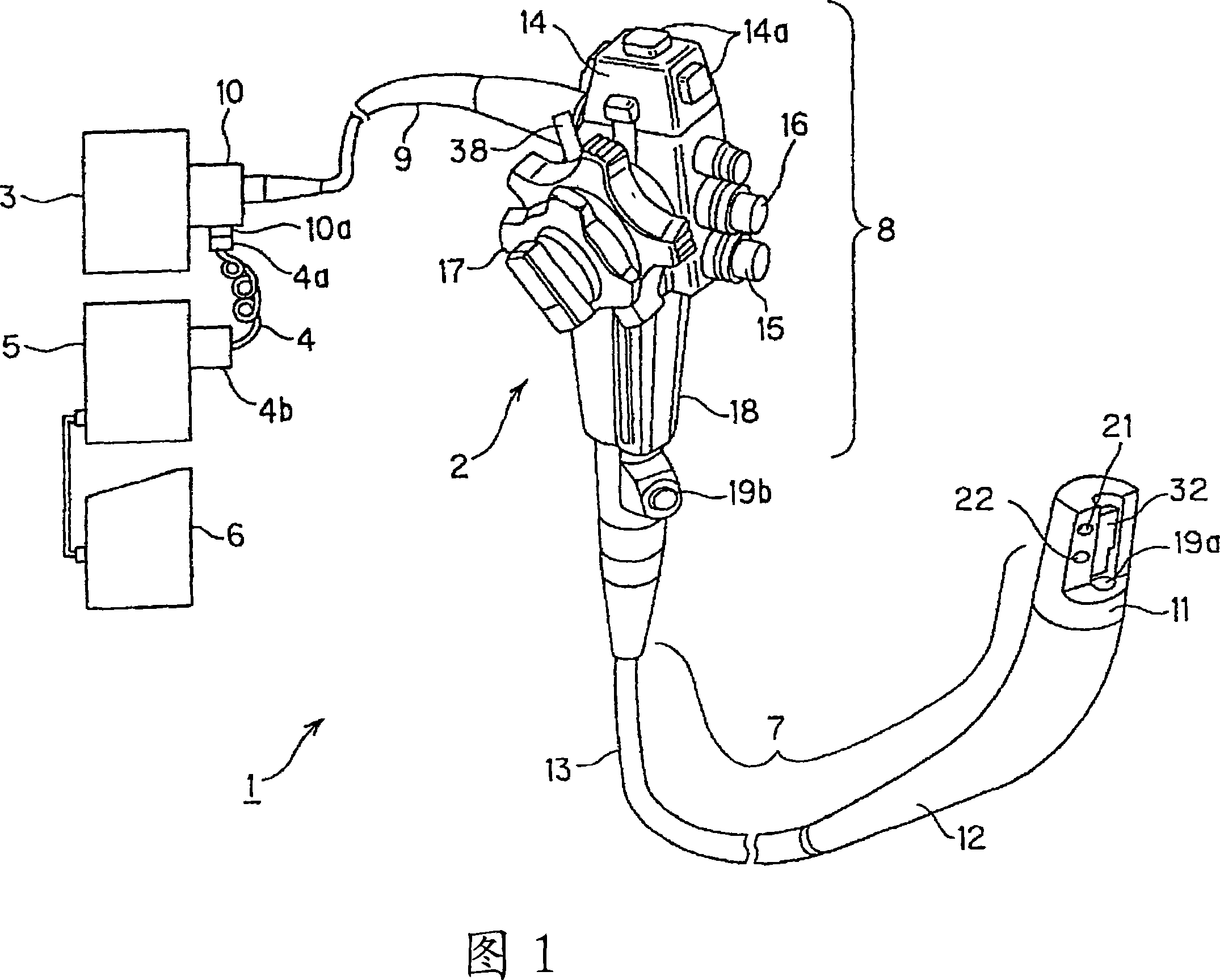
[0068] The electronic endoscope system 1 shown in FIG. 1 is composed of the following parts: an electronic endoscope 2, which constitutes Embodiment 1; a light source device 3, which is connected to the electronic endoscope 2 to supply illumination light; The processor 5 is connected to the electronic endoscope 2 through the scope cable 4, and has a built-in signal processing circuit for signal processing of the imaging device 26 (refer to FIG. 4 ) built in the electronic endoscope 2; and a monitor 6. It displays the image signal input through the monitor cable connected to the video processor 5 on the display surface in color.

[0069] This electronic endoscope 2 has: an insertion part 7, which is inserted into a body cavity or the like, and is elongated and flexible; an operation part 8, which is formed on the base end side of the insertion part 7; and a universal cord part 9, ...

Embodiment 2

[0273] Next, Embodiment 2 of the present invention will be described with reference to FIG. 31 . FIG. 31 shows the configuration of the objective optical system portion of the imaging device in Embodiment 2 of the present invention. In this embodiment, for example, the first lens 22a in the objective optical system 22 in Embodiment 1 is moved in a direction perpendicular to the axis of the lens system other than the first lens 22a to make the upper viewing angle θa larger than the lower viewing angle. θb is small.

[0274] That is, as shown in FIG. 31, the axis of the first lens 22a is moved in a direction perpendicular to the imaging optical axis O (set the moving distance to, for example, d), which is the direction on the side of the upper viewing angle (insertion portion 7 in the longitudinal direction), that is, the direction in which the illumination lens 21 of the front end 11 separates, and is fixed to the lens frame 41 with an adhesive 60 . The movement distance d, i...


PUM


Abstract

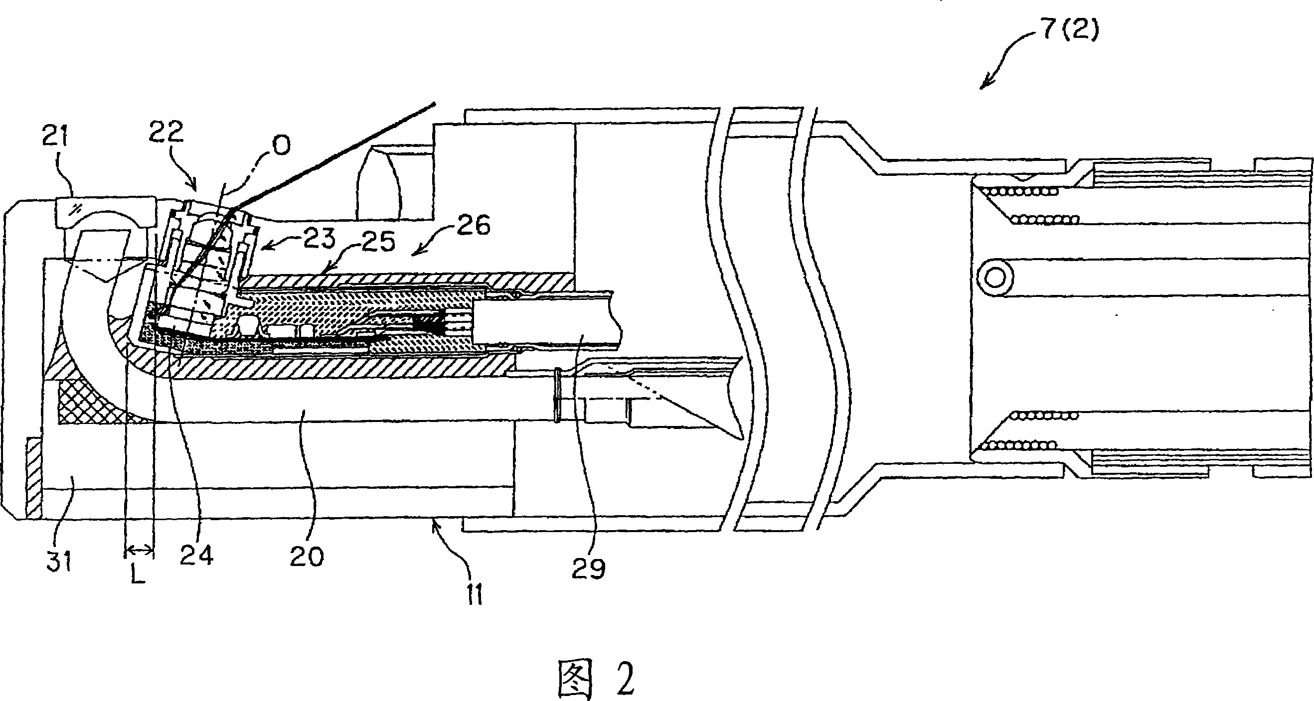
An electronic endoscope has a raising device, a solid-state imaging element, and an objective optical system. The raising device is provided on a head body at the head of an insertion section where a channel in which a treatment tool is inserted is provided and varies the direction of projection of the treatment tool near a head opening of the channel. The solid-state imaging element takes an image in a body cavity as an endoscope image. The objective optical system has a predetermined view field angle with a viewing direction at at least 90 DEG to a line segment defined by the direction from the proximal end toward the distal end of the insertion section. The objective optical system captures the treatment tool, projecting from the head opening, in a first view field angle and focuses the image in the body cavity on the solid-state imaging element. The range of the view field of the first view field angle covers the proximal end side of the insertion section, with the view field direction in the view field angle as the center. The first view field angle corresponds to an upper side view field angle in observation and is set to be equal to or less than a second view field angle that has a view field range covering the distal end side of the insertion section in the view field angle and corresponds to a lower side view field angle in the observation.

Description

technical field [0001] The present invention relates to an electronic endoscope suitable for treatment using a treatment tool. Background technique [0002] In recent years, electronic endoscopes equipped with solid-state imaging devices have been widely used in the medical field and the like. As a first prior electronic endoscope, for example, Japanese Unexamined Patent Application Publication No. 2003-230533 discloses an electronic endoscope having a side view or a rear oblique view as a viewing direction. [0003] In addition, for example, Japanese Unexamined Patent Application Publication No. 2004-72526, which is a second precedent example, discloses an electronic endoscope having a channel through which a treatment instrument can be inserted and having a side view or a rear oblique view as a field of view direction. [0004] In the above-mentioned second prior example, a wedge-shaped lens having a thicker upper viewing angle side than a lower viewing angle side is used...

Claims


Application Information

Patent Timeline
IPC IPC(8): A61B1/00
Inventor 三谷贵彦粂井一裕秋叶一芳酒井诚二一村博信河内昌宏
Owner OLYMPUS MEDICAL SYST CORP
Learn More