
Magnetic induction and resonance resistivity imaging method and device

A resistivity imaging and magnetic induction technology, applied in the field of medical imaging, to reduce the condition number, improve the resistivity accuracy, and avoid cumbersome and difficult effects.

Inactive Publication Date: 2007-06-20
INST OF ELECTRICAL ENG CHINESE ACAD OF SCI
View PDF2 Cites 7 Cited by
  • Summary
  • Abstract
  • Description
  • Claims
  • Application Information

AI Technical Summary

Problems solved by technology

[0007] (3) Overcoming the ill-conditioned nature of the inverse problem of the image reconstruction process when a pair of Helmholtz coils are excited by alternating current

Method used


Image

  • Magnetic induction and resonance resistivity imaging method and device
  • Magnetic induction and resonance resistivity imaging method and device
  • Magnetic induction and resonance resistivity imaging method and device

Examples


Embodiment Construction

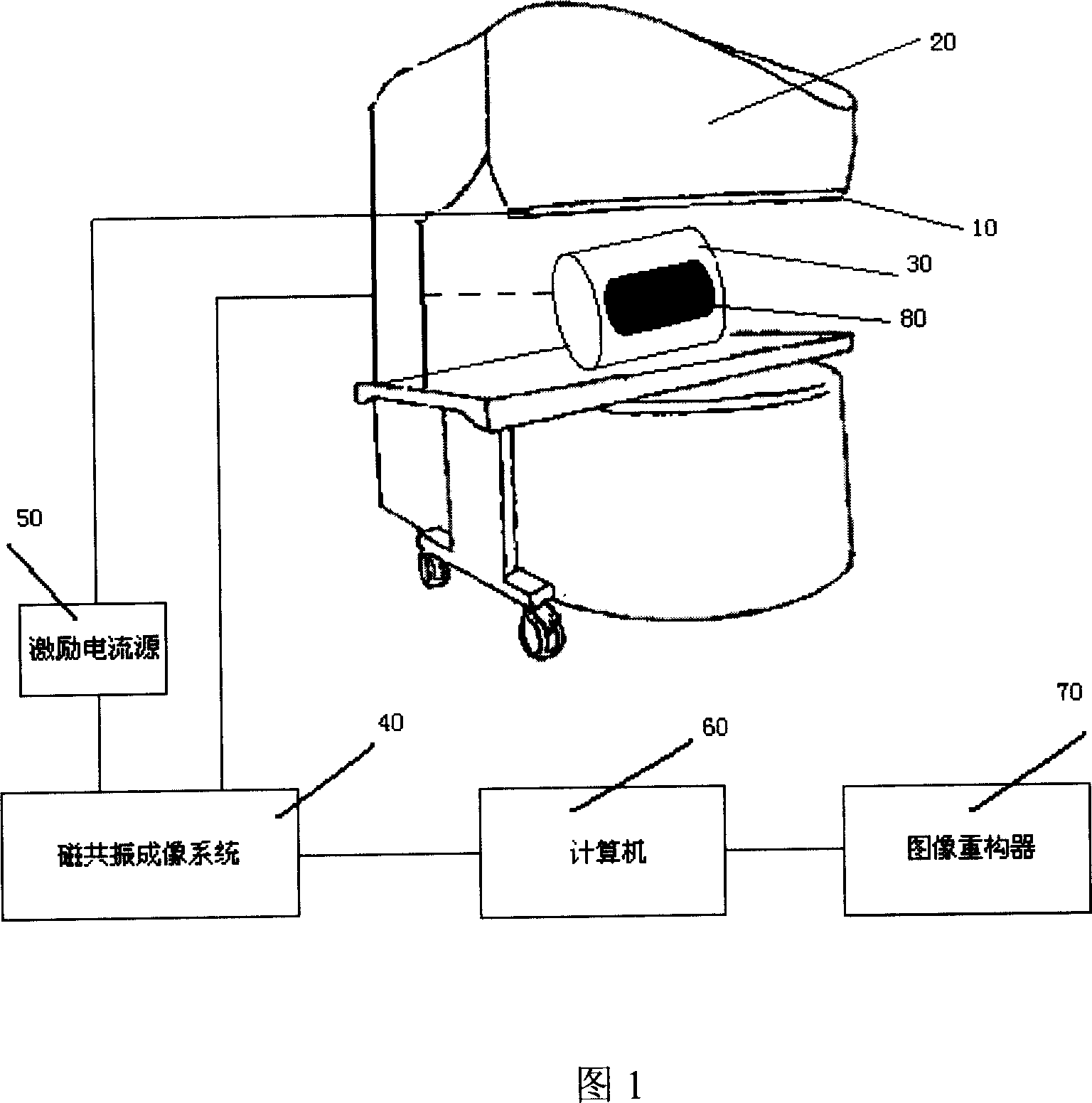
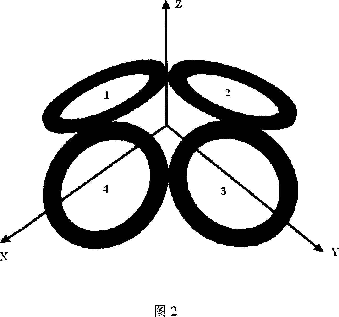
[0061] As shown in FIG. 1 , the magnetic induction magnetic resonance electrical impedance imaging device of the present invention includes an excitation current source 50 , a magnetic resonance imaging system 40 , a computer 60 , and an image reconstructor 70 . The excitation current source 50, the magnetic resonance imaging system 40, the computer 60, and the image reconstructor 70 are connected in sequence. 20 denotes a magnetic resonance imaging magnet, a radio frequency coil and a gradient coil. The excitation coil group 10 is installed on the upper pole plate of the magnetic resonance imaging magnet. As shown in Figure 2, the excitation coil group 10 is composed of four planar circular excitation coils 1, 2, 3, and 4. The coils 1, 2, 3, and 4 are symmetrically arranged in pairs tangentially. have the same angle. Each coil is connected in parallel to the excitation current source 50, the terminal voltage of the excitation current source 50 is 120V, and the maximum outpu...


PUM


Abstract

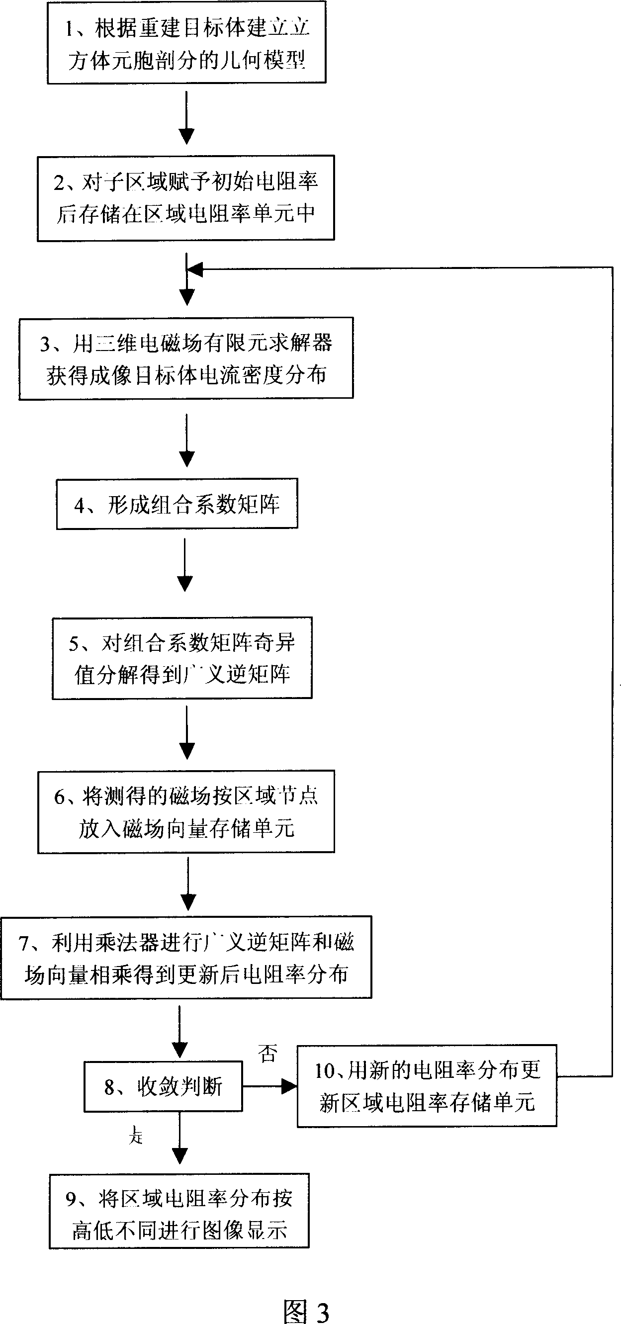
A magnetic induction type magnetic resonance resistivity imaging method with low imaging error includes such steps as generating the alternative exciting current by an exciting coil group consisting of 4 planar circular exciting coils arranged symmetrically in pairs, using magnetic resonance to obtain the phase shift caused by the components Bz of total magnetic field in the direction of master magnetic field, obtaining the distribution of Bz from the difference between said phase shift and the phase shift of non-current exciting coil group, and obtaining the resistivity image of the object to be imaged according to the non-linear relation between component Bz and resistivity. Its apparatus is also disclosed.

Description

technical field [0001] The invention relates to a medical imaging method, in particular to an impedance imaging method and device using magnetic resonance imaging technology and magnetic induction principle. Background technique [0002] The traditional magnetic resonance electrical impedance imaging method (such as US patent: US6,397,095 B1) uses the excitation electrode to inject current into the imaging target body, measures the voltage at the boundary of the target body through the measuring electrode, and detects the injected current in the imaging target body through magnetic resonance technology. The generated magnetic field distribution is used to reconstruct the impedance distribution image of the imaging target by using the surface voltage and the magnetic field information inside the imaging target to apply the equipotential line back projection method. This magnetic resonance electrical impedance imaging method has the following problems, mainly: (1) the electrod...

Claims


Application Information

Patent Timeline
IPC IPC(8): A61B5/055A61B5/053
Inventor 刘国强蒙萌王涛王新立王浩
Owner INST OF ELECTRICAL ENG CHINESE ACAD OF SCI
Learn More