Elevator and emergency braking device for the same

An emergency braking and elevator technology, applied in the field of elevators, can solve problems such as one-end contact and achieve the effect of preventing damage

Inactive Publication Date: 2011-01-26
HITACHI LTD
View PDF2 Cites 0 Cited by
  • Summary
  • Abstract
  • Description
  • Claims
  • Application Information

AI Technical Summary

Problems solved by technology

As a result, the contact between the guide rail and the ceramic brake pad may become one-end contact

Method used


Image

  • Elevator and emergency braking device for the same
  • Elevator and emergency braking device for the same
  • Elevator and emergency braking device for the same

Examples


Embodiment Construction

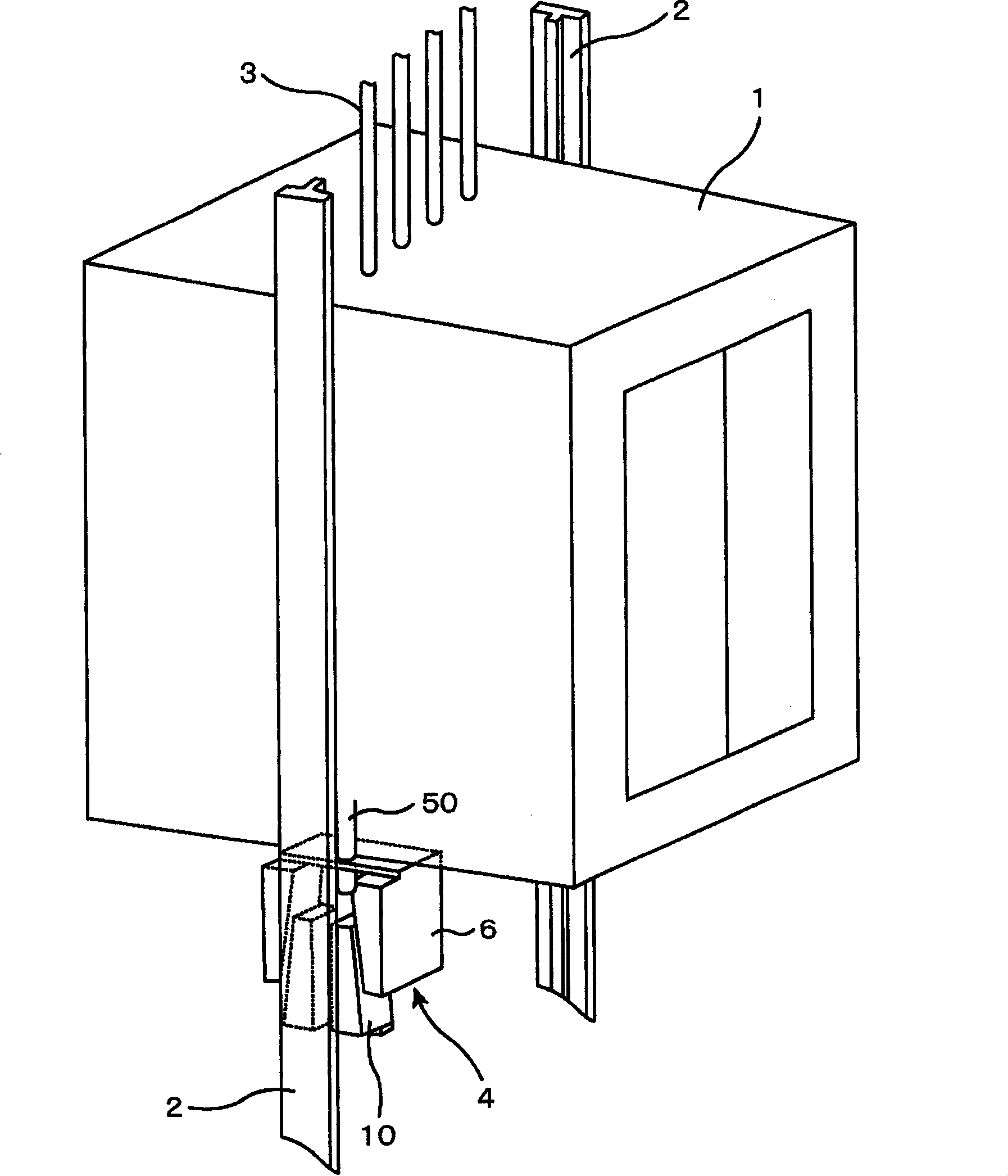
[0038] Hereinafter, an embodiment of the elevator according to the present invention and the emergency braking device used in the elevator will be described with reference to the drawings. figure 1 It is a perspective view of an elevator car 1 of the elevator and an emergency braking device installed in the lower part of the elevator car. The elevator car 1 for passengers is connected to a drive system (not shown) on the uppermost floor of the building via a sling 3. At that figure 1 In order to facilitate understanding, detailed illustrations of the elevator door opening and closing mechanism and the outer frame are omitted. On both sides of the hoistway 60, a pair of guide rails 2 and 2 are provided for guiding the elevator car 1 when it goes up and down.

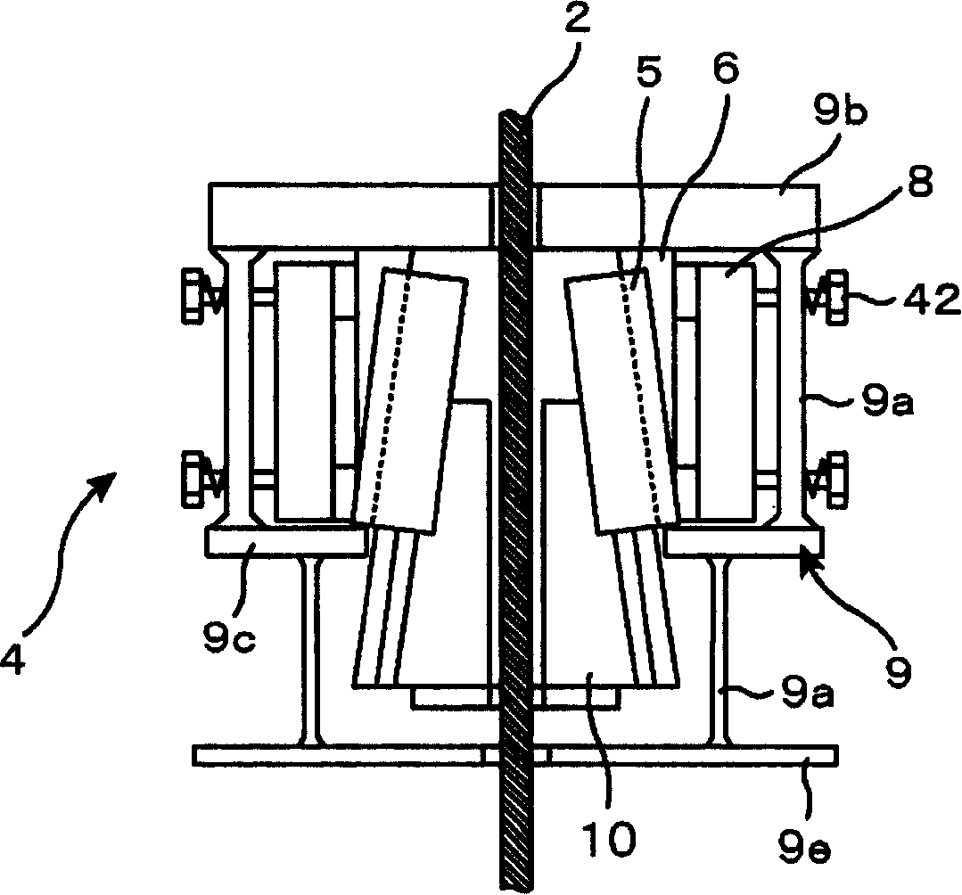
[0039] A pair of emergency braking devices 4, 4 are provided at the bottom of the elevator car 1. The pair of emergency brakes sandwiches the T-shaped longitudinal rods of the guide rails 2 and 2 each having a T-shaped cros...


PUM


Abstract

In order to prevent the damage of a slide surface of a ceramics friction material which is possessed by a braking element for an emergency brake device for an elevator, and stop an elevator car efficietly at need, the emergency brake device for an elevator can hold a guide (2) provided on a lifting passage wall of the elevator. The braking element (10) is arraged at the bottom of the elevator car(1). When the elevator car runs in a speed exceed a determined speed, a push element pushes the braking element on the guide. A plurality of concaves with of without bottoms are formed on the brakingelement, and the ceramics friction material (12) are housed in the concaves. While mounting the friction material on the braking element, a plane (14) is formed by the lower portion of the friction material which one side end oppositing to the guide, and the upper portion is formed as a tilting surface (13) or a curved surface separating with the guide.

Description

Technical field [0001] The present invention relates to an elevator, in particular to an emergency braking device for an elevator that operates when the speed of the elevator exceeds a predetermined speed. Background technique [0002] Patent Document 1 Japanese Patent Laid-Open No. 10-182031 discloses an example of an emergency braking device as a safety device. When the elevator car falls due to the sling used to drive the elevator is cut, etc. , The emergency braking device stops the elevator car with appropriate deceleration. In the emergency braking device described in this publication, in order to obtain heat resistance exceeding 1000°C and maintain stable braking characteristics at high speeds and high response speeds, a brake body and brake pads are provided. The sheet is arranged on the braking surface side of the main body brake, and is embedded with a protruding portion protruding from the surface, and the protruding portion is cylindrical or a polygonal column with c...

Claims


Application Information

Patent Timeline
Patent Type & Authority Patents(China)
IPC IPC(8): B66B5/22
Inventor 佐藤五郎中山真人岩佐正明宫田弘市大森贡
Owner HITACHI LTD
Why Eureka
Try Eureka