Hollow structural component

A technology of hollow components and hollow walls, which is applied to building components, building structures, floor slabs, etc., can solve the problems of high transportation costs, increased production costs of thin-walled boxes, construction costs of cast-in-place reinforced concrete hollow slabs, and large space occupation

Inactive Publication Date: 2007-06-20
湖南邱则有专利战略策划有限公司
View PDF2 Cites 0 Cited by
  • Summary
  • Abstract
  • Description
  • Claims
  • Application Information

AI Technical Summary

Problems solved by technology

However, this kind of thin-walled box mold car shell component, as a whole thin-walled box component, takes up a lot of space during transportation, the quantity of each transportation is small, and the transportation cost is high...

Method used


Image

  • Hollow structural component
  • Hollow structural component
  • Hollow structural component

Examples


Embodiment Construction

[0034] The present invention will be further described below in conjunction with the accompanying drawings and embodiments.

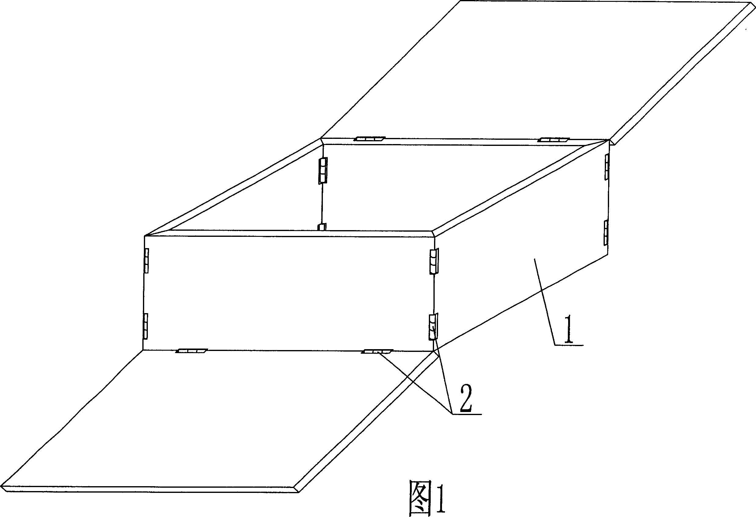
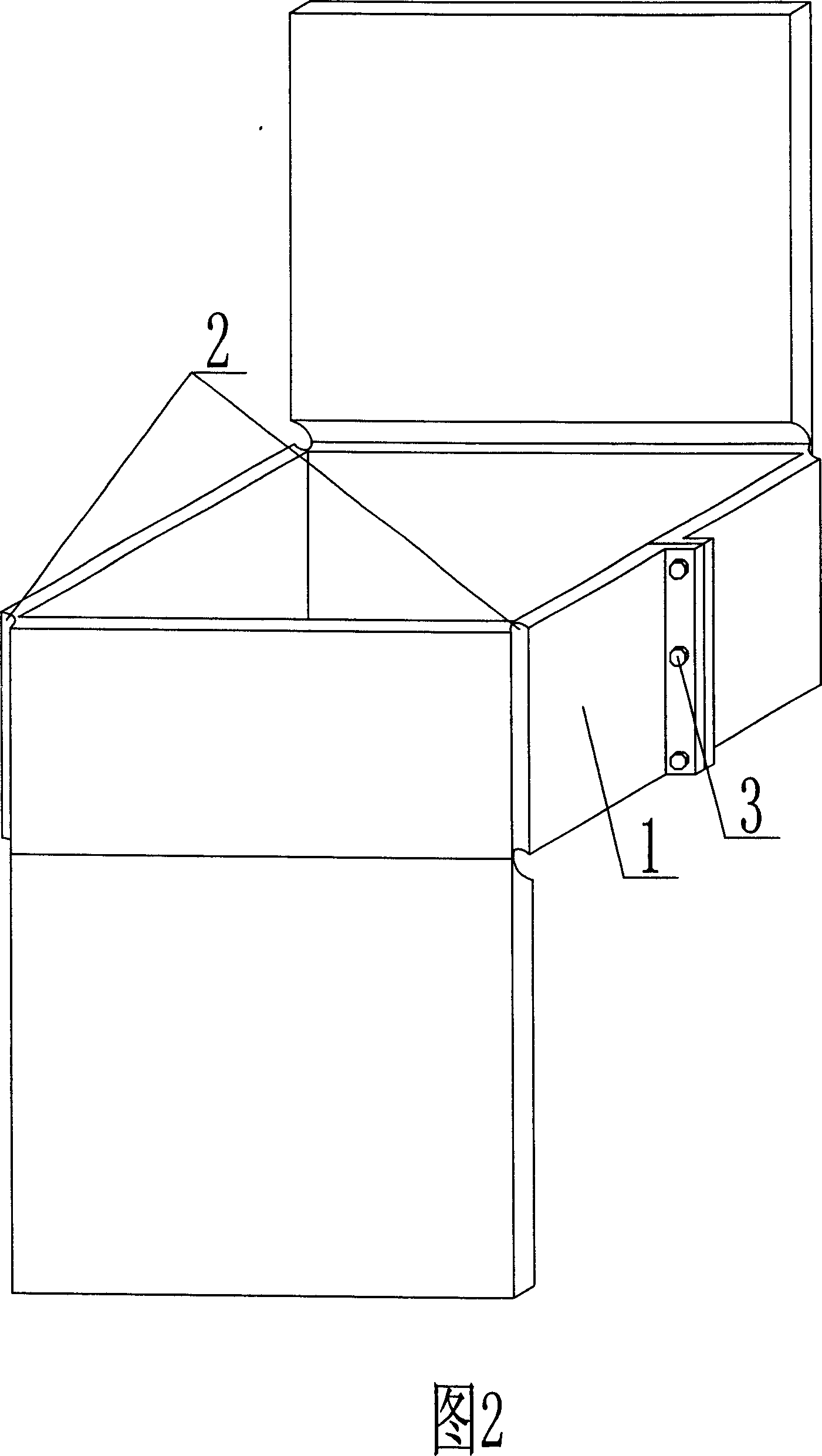
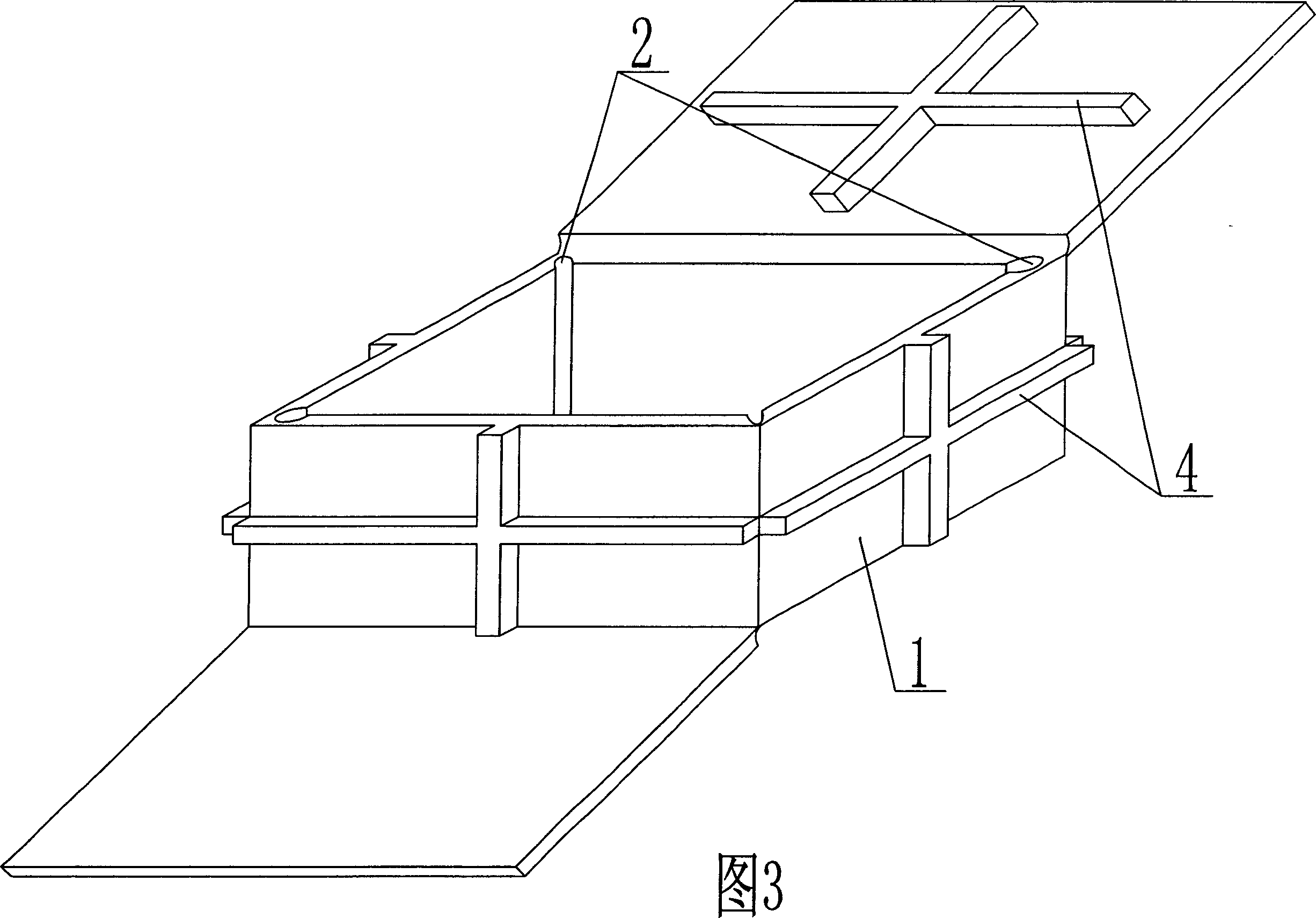
[0035] As shown in the accompanying drawings, the present invention includes a polyhedral outer wall 1, the outer wall 1 encloses a cavity polyhedron, and is characterized in that the intersecting line of the outer wall 1 is a hinge 2, and there are parallel or intersecting hinges on the inner or outer surface of the outer wall 1. T-shaped rib 4. As shown in Figure 5, the hollow member includes a polyhedral outer wall 1, the outer wall 1 encloses a cavity polyhedron, the intersecting line of the outer wall 1 is a hinge 2, and there are intersecting T-shaped ribs 4 on the inner surface of the outer wall 1.

[0036] As shown in the accompanying drawings, the present invention includes a polyhedral outer wall 1, which forms a polyhedral cavity enclosed by the outer wall 1, and is characterized in that the outer wall 1 is a double wall, wherein at least one...


PUM


Abstract

A hollow member is composed of polyhedral external wall(1), cavity polyhedron(3), hinge(2) and T-shaped reinforcing rib(4). Said polyhedral external wall(1) encloses cavity polyhedron(3), intersecting line of said external wall(1) is hinge(2), parallel or intersected T-shaped reinforcing rib(4) are arranged on internal or external surface of said external wall(1). It can be used for various hollow plates of cast-in-situ reinforced concrete or pre-stressed reinforced concrete, hollow beamless building roof, basic baseboard, wall and bridges.

Description

(1) Technical field [0001] The invention relates to a hollow component. (2) Background technology [0002] At present, in the prior art, the hole-forming member of the cast-in-place reinforced concrete hollow slab is a permanent mandrel, such as paper tubes, plastic tubes, metal bellows, hollow form shells, and lightweight materials for mandrels. These tubular mandrels or hollow components are mainly considered to evacuate the concrete and reduce the weight of the hollow slab. For example, the patent No. ZL99249798.1, which the applicant applied for on November 29, 1999, is a utility model patent named "fiber-reinforced thin-walled member for reinforced concrete filling", which discloses a thin-walled formwork member, including an upper plate, The surrounding side walls, the lower bottom, and the upper plate, the surrounding side walls and the lower bottom form a polyhedral cavity. Another example is that the application number applied by the applicant on November 23, 2001...

Claims


Application Information

Patent Timeline
IPC IPC(8): E04B5/16E04B5/36E04C1/00
Inventor 邱则有
Owner 湖南邱则有专利战略策划有限公司
Why Eureka
Try Eureka