

Air-inlet fast joint of pneumatic tool
A technology of pneumatic tools and air inlets, applied in the direction of pipes/pipe joints/fittings, adjustable connections, passing elements, etc., which can solve the problems of loss of leak-proof effect, loss of effectiveness of leak-proof devices, and inability to achieve complete leak-proof, etc. To achieve the effect of improving flexibility and practicality
- Summary
- Abstract
- Description
- Claims
- Application Information
AI Technical Summary
Problems solved by technology
Method used
Image

Examples
Embodiment Construction
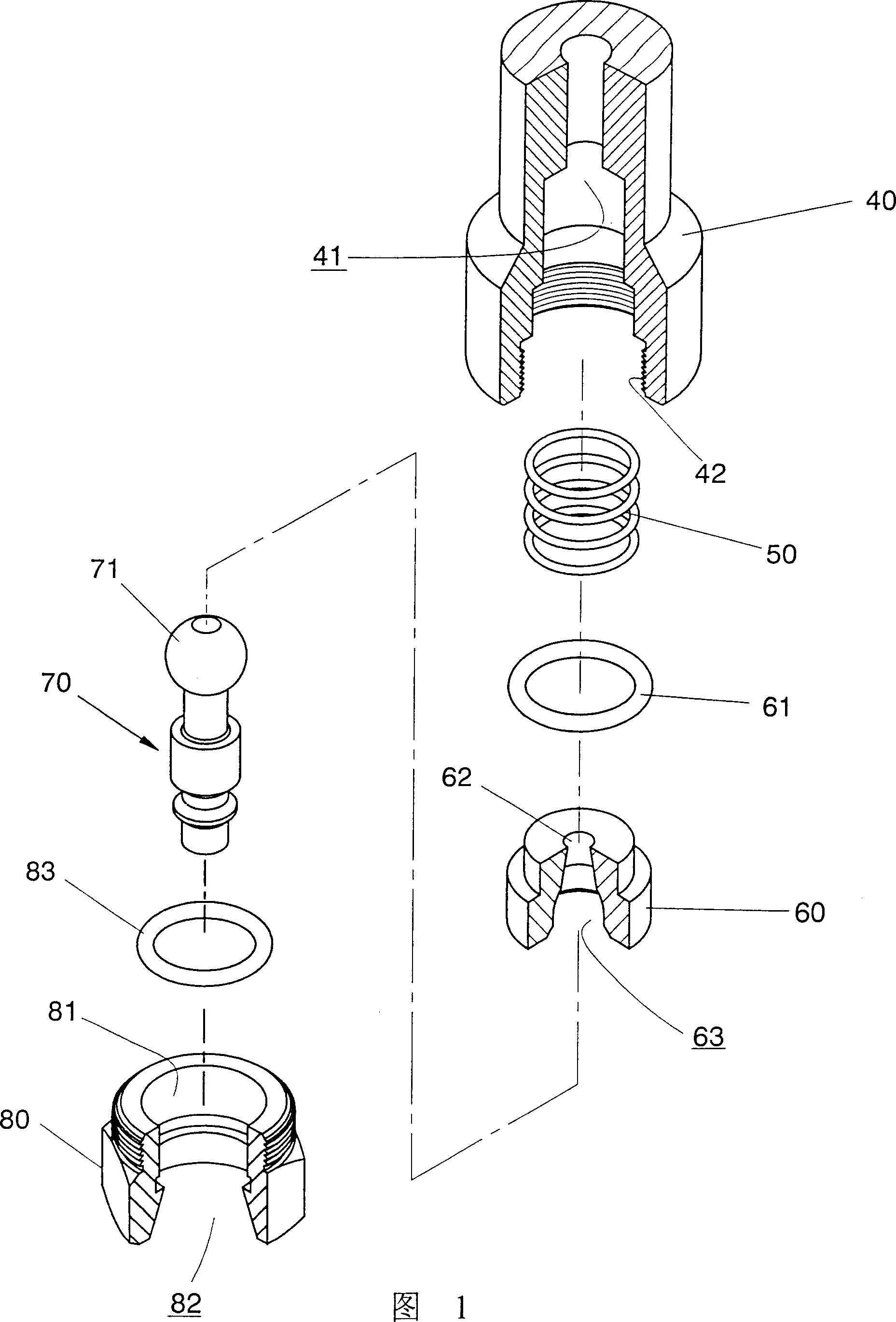
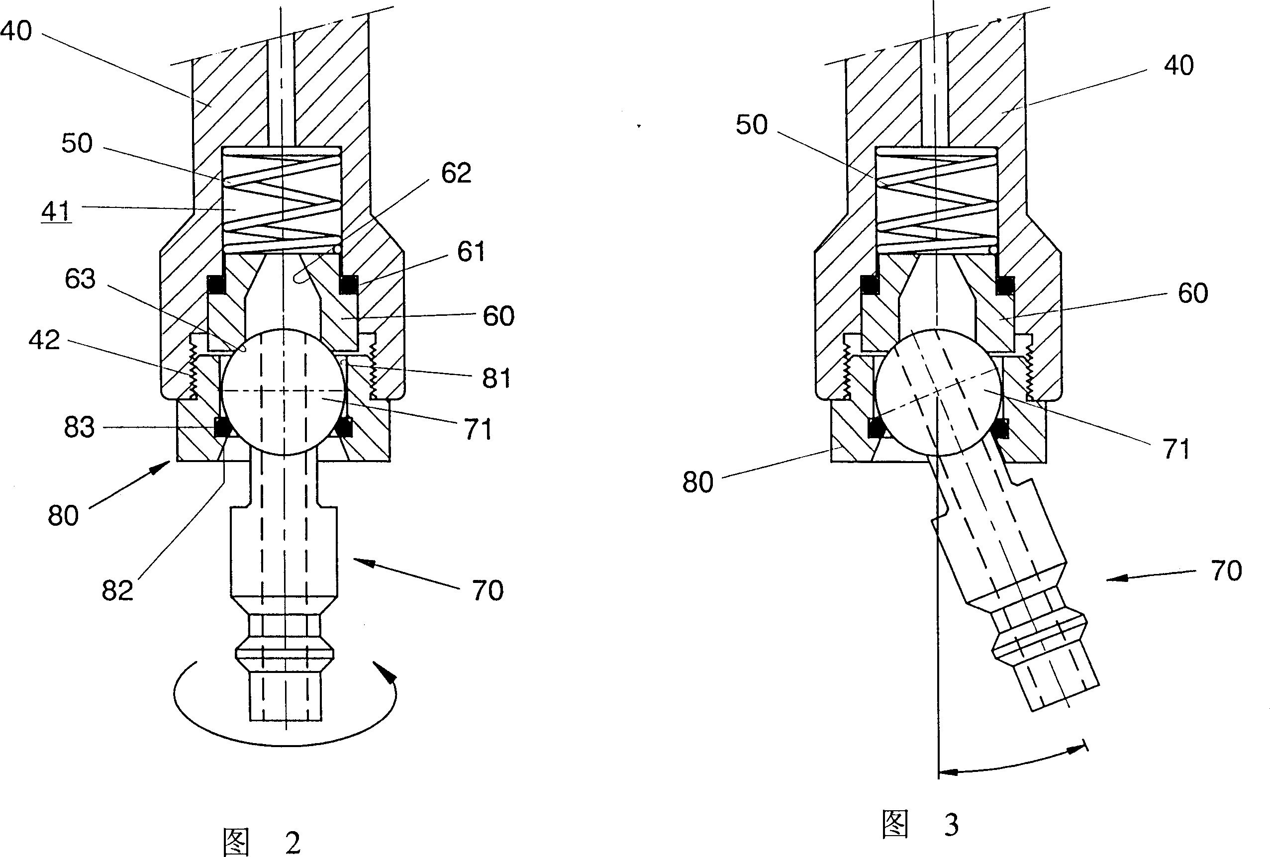
[0031] As shown in Figure 1 and Figure 2, the quick connector of the air inlet of the pneumatic tool provided by the present invention mainly includes:
[0032] A pneumatic tool 40, the bottom of the pneumatic tool 40 is provided with a spring hole 41, and an elastic component 50 is placed in it, and one end of the elastic component 50 abuts against a leak-proof piston 60, and the bottom port of the pneumatic tool 40 is provided with an inner screw hole 42 .
[0033] A leak-proof piston 60, which is made of soft material, is covered with an O-ring 61 to seal the leak-proof piston 60 and the spring hole 41, and one end of the leak-proof piston 60 is set to gradually expand from the outside to the inside. The tapered hole 62 is increased (smaller on the outside and larger on the inside), and a circular socket 63 is provided at the other port. The arc curvature of the circular socket 63 is the same as that of the sphere 71 of the male joint 70 .
[0034] A ball 71 at one end of ...
PUM
 Abstract
Description
Claims
Application Information