Method for controlling an electronic power converter that is connected to a direct-current source

A technology of DC voltage source and converter, which is applied in the direction of converting AC power input into AC power output, output power conversion device, electrical components, etc.

Inactive Publication Date: 2007-06-20
SIEMENS AG
View PDF1 Cites 0 Cited by
  • Summary
  • Abstract
  • Description
  • Claims
  • Application Information

AI Technical Summary

Problems solved by technology

[0013] The invention solves the above-mentioned technical problem by means of a method for regulating a converter connected to a DC voltage source, the converter having a disconnectable Power semiconductor switches, wherein the current flowing through each power semiconductor switch is measured under the condition of obtaining the current values ​​respectively corresponding to these power semiconductor switches, the current value is sampled, and the sampling is performed under the condition of obtaining the digital current value The final current value is digitized and checked by a logic implemented in the regulation unit for the occurrence of an overcurrent condition, wherein, if the overcurrent condition is not met, the regulation is switched on by means of nominal operation and disconnecting said power semiconductor switch, and in the case of an overcurrent condition, at least disconnecting the power semiconductor switch loaded with a digital current value satisfying the overcurrent condition, after a pulse blocking duration has elapsed and after satisfying the overcurrent condition Under the condition of the digital current value of the current condition, turn on all the power semiconductor switches connected to the positive DC terminal and disconnect all the power semiconductor switches connected to the negative DC terminal, or vice versa, and among them, if the digital current value does not meet the overcurrent condition Under the condition of the current value, the regulation of the power semiconductor switch is realized through the regulation of the rated operation again

Method used


Image

  • Method for controlling an electronic power converter that is connected to a direct-current source
  • Method for controlling an electronic power converter that is connected to a direct-current source
  • Method for controlling an electronic power converter that is connected to a direct-current source

Examples


Embodiment Construction

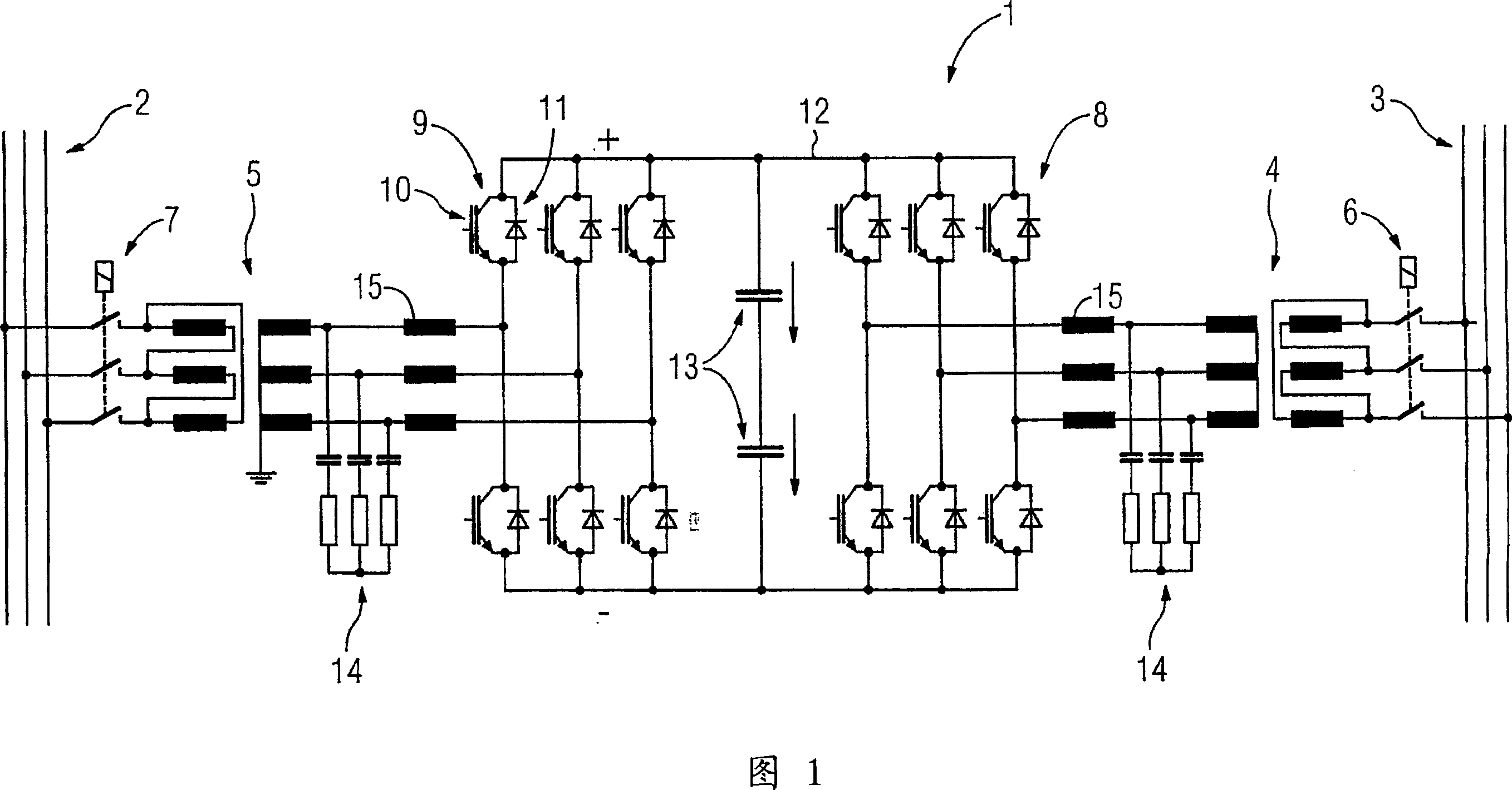
[0026] FIG. 1 shows a DC grid coupling 1 for supplying an isolated grid 2 via a supply grid 3 . The power supply grid 3 is connected to the high voltage DC bridge 1 through a transformer 4 and the isolated grid 2 is connected to the high voltage DC bridge 1 through a transformer 5 , wherein the switches 6 and 7 are configured to disconnect the high voltage DC bridge 1 from the power supply grid 3 and the isolated grid 2 respectively.

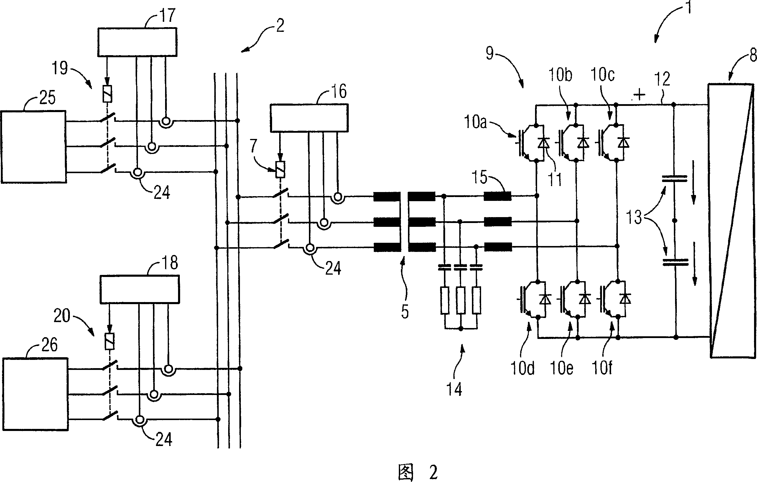
[0027] The DC grid coupling 1 has two converters with self-guiding power semiconductor switches 10 in the form of a six-pulse bridge circuit (6-puls-Brueckenschaltung). A freewheeling diode is arranged in the parallel connection of each power semiconductor switch 10 . The converters 8 and 9 are connected to each other via a DC intermediate circuit 12 which is connected to each other forming a positive DC terminal marked with a "+" sign and a negative DC terminal marked with a "-" sign. An energy store in the form of a capacitor 13 is connected ...


PUM


Abstract

The invention relates to a method for controlling an electronic power converter (9), which is connected to a direct-current source (12), comprises power conductor switches (10a...10f) that can be deactivated and which is designed to supply a distribution network (2) with three-phase voltage. According to said method, the currents that flow through the respective power semiconductor switches (10a...10f) are measured, whereby current values that are respectively assigned to the power semiconductor switches (10a...10f) are obtained, the current values are sampled and the sampled current values are digitised to obtain digital current values, the latter being checked by a logic that is implemented in a control unit for the presence of an excess current condition. If no excess current condition is detected, the power semiconductor switches (10a...10f) are activated and deactivated with the aid of a nominal operation controller and if an excess current condition is detected, at least the power semiconductor switches with assigned digital current values that fulfil the excess current condition are deactivated after a pulse block has expired. For the digital current values that fulfil the excess current condition, all power semiconductor switches (10a...10f), which are connected to the positive direct-current connection, are activated and all power semiconductor switches, which are connected to the negative direct-current connection are deactivated or vice versa. For the digital current values that do not fulfil the excess current condition, The power semiconductor switches (10a...10f) are controlled once again by the nominal operation controller.

Description

technical field [0001] The invention relates to a method for regulating a converter connected to a DC voltage source, the converter having disconnectable power semiconductor switches which are designed to provide a three-phase voltage for a distribution network. Background technique [0002] A method for regulating a DC voltage converter is known, for example, from High Voltage Direct Current Transmission. HVDC transmission is used on the one hand to transmit electrical energy over long distances. Another application involves, for example, the coupling of grids with different three-phase voltage frequencies. For HVDC transmission, the two converters are connected to each other via a DC link or a DC link. The converters are each connected to a three-phase voltage grid and essentially consist of power semiconductor switches. Self-guiding (selbstgefuehrt) converters, ie converters with self-guiding power semiconductor switches, are increasingly used in grid coupling. This a...

Claims


Application Information

Patent Timeline
Patent Type & Authority Applications(China)
IPC IPC(8): H02M5/458H02J3/34H02J3/36
CPCH02J3/36H02J3/34Y02E60/60H02M5/458
Inventor 乔尔格·弗洛特梅希迈克尔·温霍尔德雷纳·朱罗夫斯基
Owner SIEMENS AG
Why Eureka
Try Eureka