Air conditioner for accurately control temperature and humidity

A precise control, temperature and humidity technology, applied in the control/regulation system, temperature control, humidity control, etc., can solve problems such as high energy consumption, hidden dangers of compressor life, and achieve the effects of improving accuracy, reducing frequent starts, and reducing impact

Active Publication Date: 2007-06-27
上海约顿机房设备有限公司
View PDF0 Cites 10 Cited by
  • Summary
  • Abstract
  • Description
  • Claims
  • Application Information

AI Technical Summary

Problems solved by technology

[0005] Therefore, generally speaking, the current constant temperature and humidity air conditioners have the following three shortcomings: 1. The hidden danger of compressor life during refrigeration

Method used


Image

  • Air conditioner for accurately control temperature and humidity
  • Air conditioner for accurately control temperature and humidity

Examples


Embodiment Construction

[0015] The present invention will be further described below in conjunction with the accompanying drawings and embodiments.

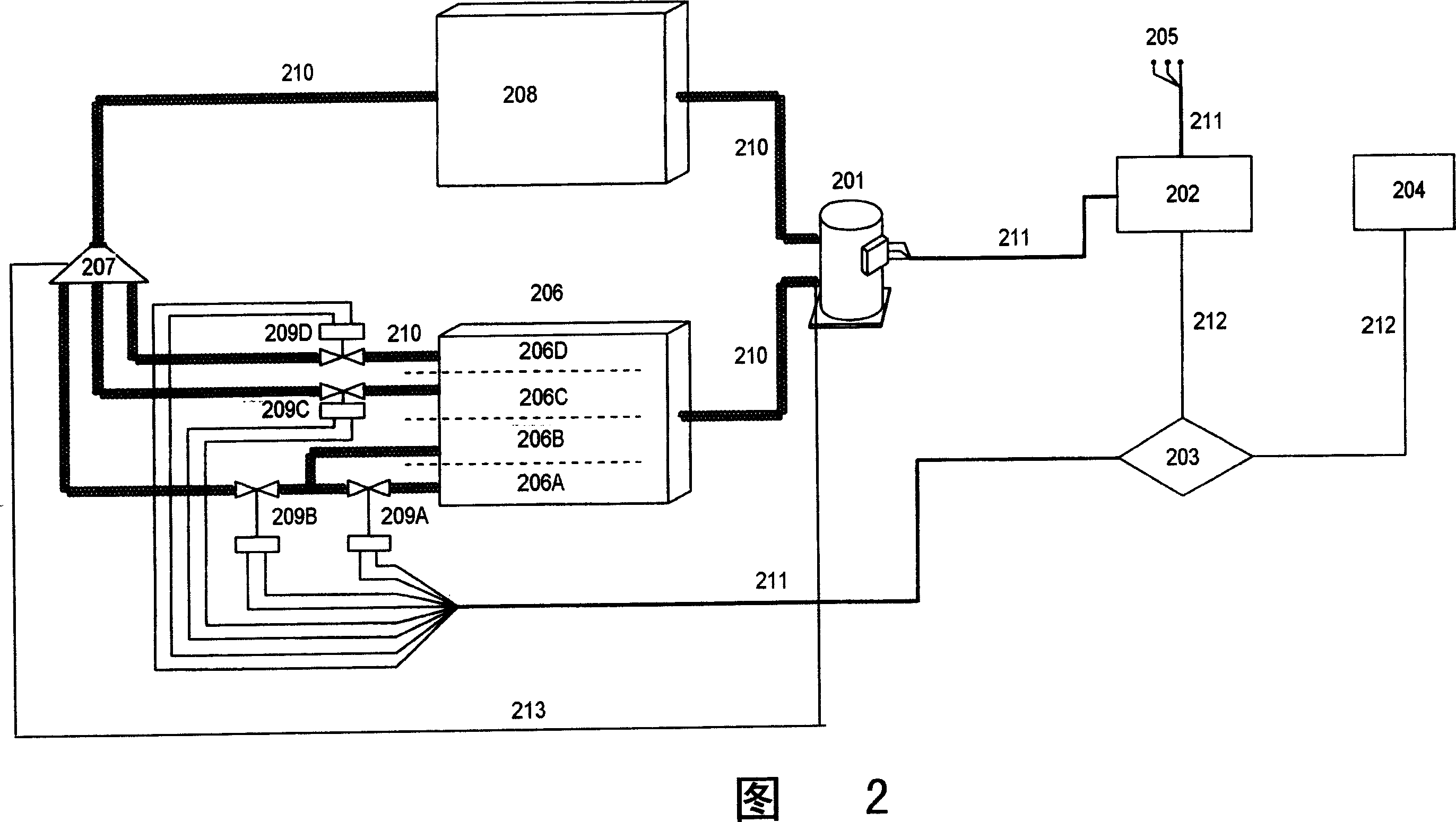
[0016] Fig. 2 shows the internal principle structure of a preferred embodiment of the present invention. As shown in Figure 2, the constant temperature and humidity air conditioner is mainly composed of two parts: a control device and a refrigerant working device. In the control device, the sensor 204 , the control logic unit 203 and the instruction compilation and execution unit 202 are connected through an electronic circuit 212 . The sensor 204 is generally a temperature sensor or a humidity sensor or a combination of both, and is used to collect the temperature and humidity state of the indoor environment. The control logic unit 203 is a chip, and a program is embedded in the chip, which can set various parameters of the air conditioning system according to the ambient temperature and humidity detected by the sensor 204 and the temperature and humi...


PUM


Abstract

An air conditioner able to precisely control temp and humidity for making the temp and humidity constant has a compressor for regulating the output of refrigerant, an expansion valve for regulating the flow of refrigerant flowing in evaporator, a condenser, an evaporator with multiple segments of heat exchanging surface controlled by electromagnetic valves, ambient temp and humidity sensors, a controller, and a refrigerating pipeline.

Description

technical field [0001] The invention relates to a constant temperature and humidity air conditioner, in particular to a constant temperature and humidity air conditioner capable of precisely controlling temperature and humidity. Background technique [0002] Currently known constant temperature and humidity air conditioners have four basic functions of refrigeration, heating, humidification and dehumidification. Figure 1 shows the working principle of this air conditioning refrigeration. As shown in the figure, the refrigeration working parts of the air conditioner are mainly composed of a compressor 11, a condenser 12, an expansion valve 13 and an evaporator 14 which are sequentially connected through refrigerant pipelines. [0003] From the perspective of air conditioner operation, when the room temperature is higher than the set temperature of the air conditioner, the air conditioner activates the compressor 11 for cooling output; when the room temperature drops to meet ...

Claims


Application Information

Patent Timeline
IPC IPC(8): F24F11/02G05D22/00G05D23/00
Inventor 陈一平
Owner 上海约顿机房设备有限公司
Why Eureka
Try Eureka