Method for directly detecting underground petroleum, natural gas and coal layer gas

A natural gas and coalbed methane technology, applied in the field of direct oil detection, can solve problems such as unpredictable oil

Inactive Publication Date: 2007-06-27
陈信平
View PDF1 Cites 18 Cited by
  • Summary
  • Abstract
  • Description
  • Claims
  • Application Information

AI Technical Summary

Problems solved by technology

[0006] So far, all methods of direct oil and gas detection using seismic am

Method used


Image

  • Method for directly detecting underground petroleum, natural gas and coal layer gas
  • Method for directly detecting underground petroleum, natural gas and coal layer gas
  • Method for directly detecting underground petroleum, natural gas and coal layer gas

Examples


Embodiment Construction

[0057] The present invention will be further described below in combination with specific embodiments.

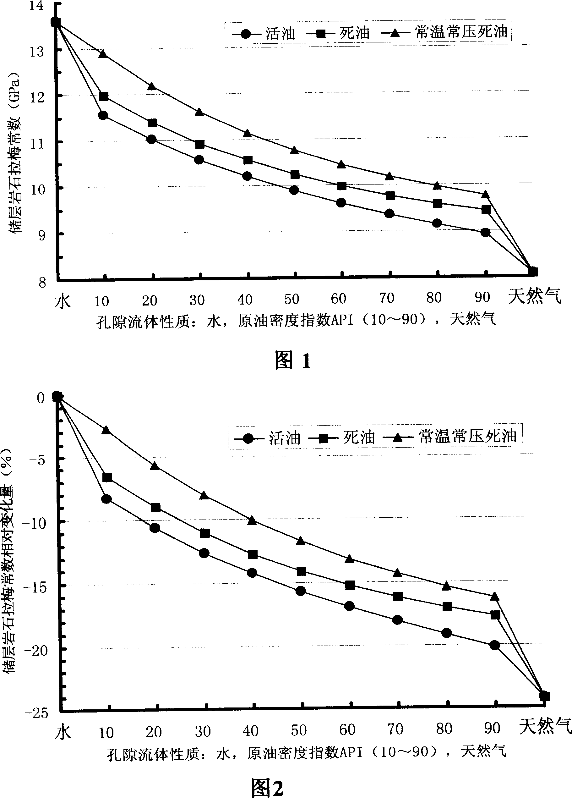
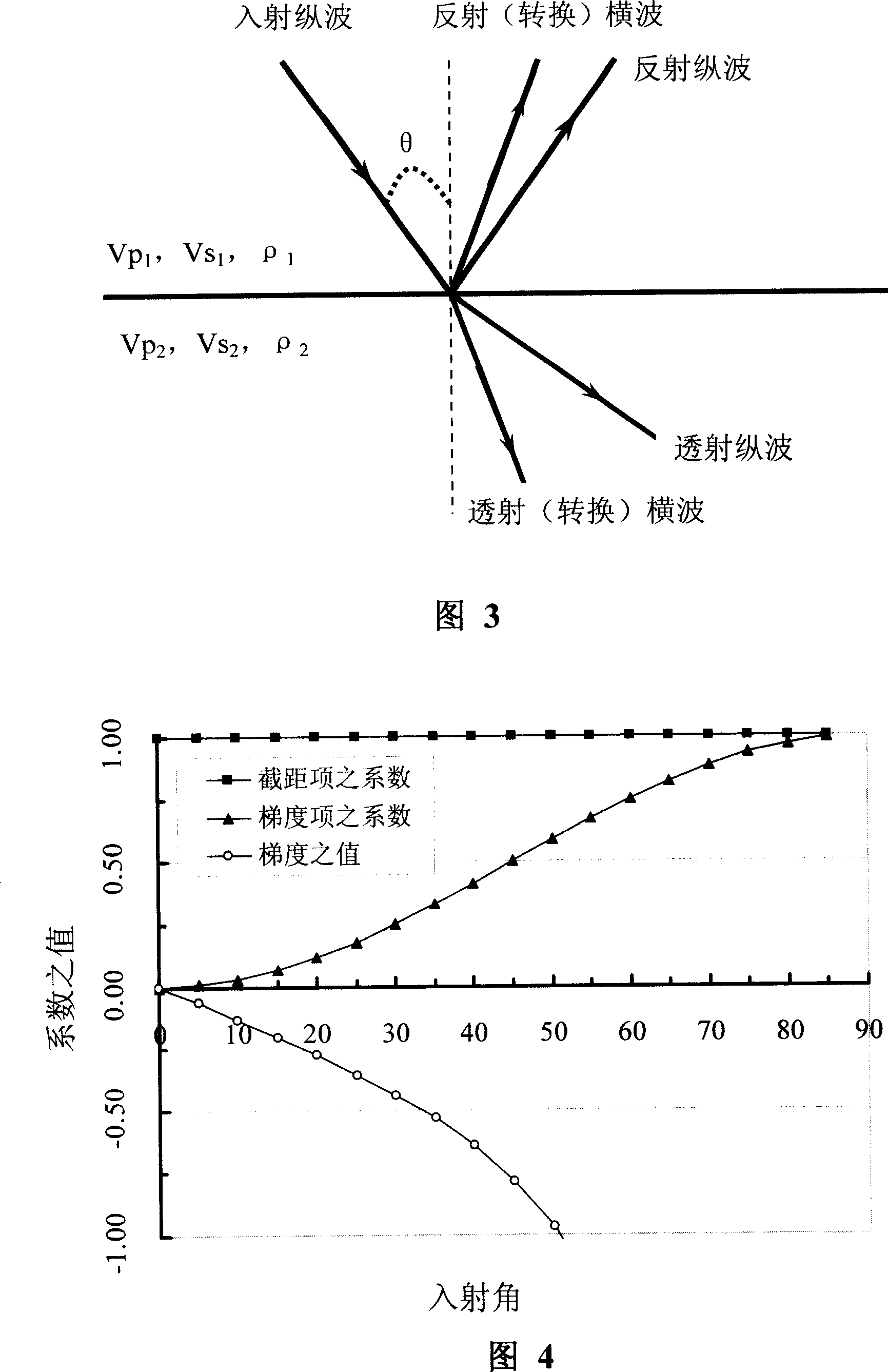
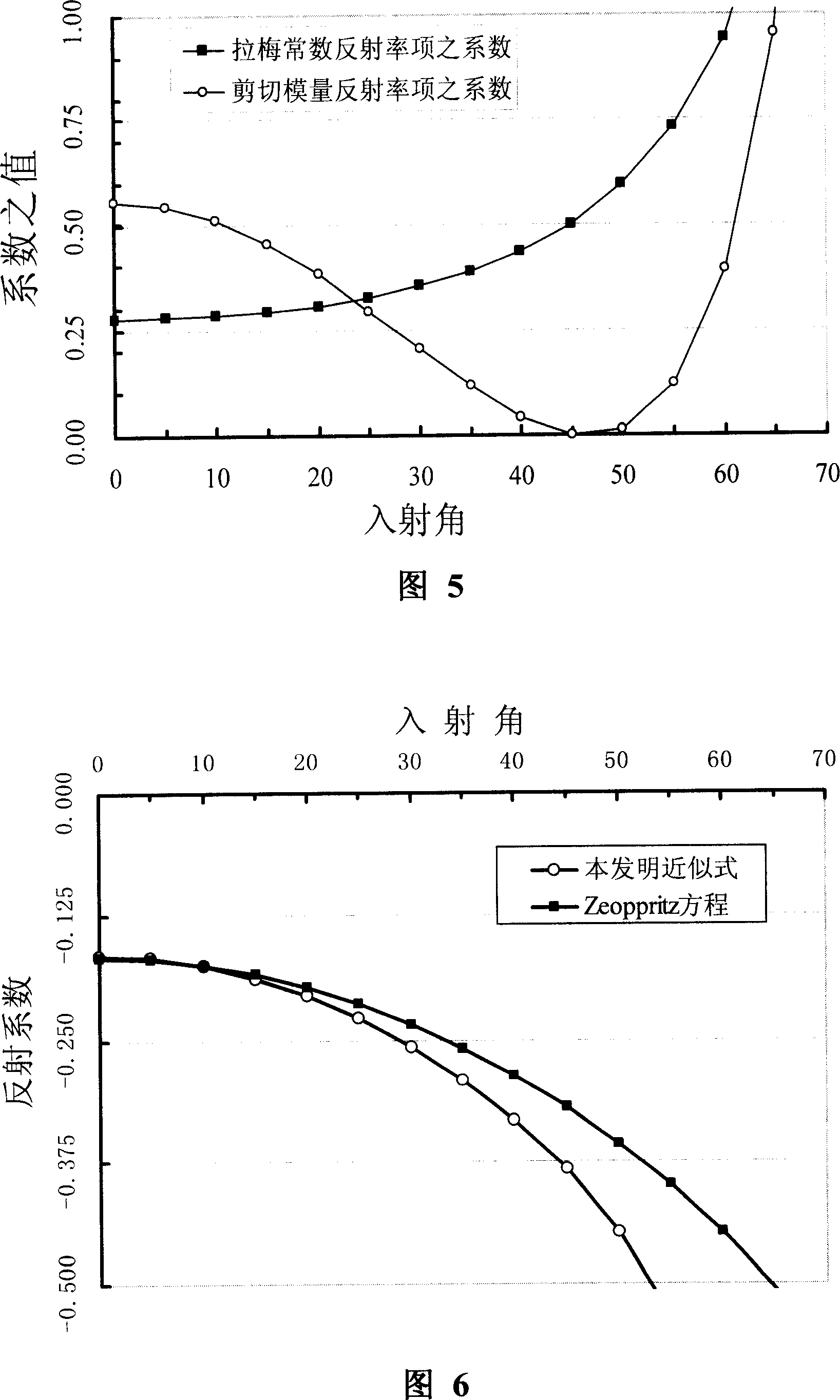
[0058] The direct hydrocarbon detection factors provided by the present invention are Lame constant reflectivity Δλ / (λ+2μ), shear modulus reflectivity Δμ / (λ+2μ) and Δμ / [κ+(4 / 3)μ], Bulk compressive modulus reflectance Δκ / [κ+(4 / 3)μ], difference between Lame constant reflectivity and shear modulus reflectivity [(Δλ-Δμ) / (λ+2μ)], Lame constant The sum of reflectivity and shear modulus reflectivity [(Δλ+Δμ) / (λ+2μ)].

[0059] In order to demonstrate the functionality of the direct hydrocarbon detectors provided by the present invention to predict oil and gas, in particular, to demonstrate the functionality of these direct hydrocarbon detectors to predict petroleum reservoirs, a method using the Gassmann equation needs to be developed. The Gassmann equation in rock physics is as follows (cf. Gassmann, F., 1951, "Elastic waves through a packing ofspheres", Geophysics , Vol.16, p.6...


PUM


Abstract

Especially, the invention is related to method for exploring petroleum. The direct carbon hydrogen detection factor utilized is Lame's constant reflectivity, shear modulus reflectivity, compressive bulk modulus reflectivity, difference between Lame's constant reflectivity and shear modulus reflectivity, and summation of Lame's constant reflectivity and shear modulus reflectivity. When the method determines the direct carbon hydrogen detection factor, approximate formula of longitudinal wave reflection coefficient in Zeoppritz combined equations utilized in the method is first approximate formula and second approximate formula.

Description

technical field [0001] The present invention relates to a method for directly detecting oil, natural gas and coalbed methane, in particular, the present invention relates to a method for determining the reflectivity of the elastic modulus of underground strata, and using these reflectivity as basic parameters to form direct hydrocarbon detection factors , a method for directly detecting oil, natural gas and coalbed methane, especially a method for directly detecting oil. Background technique [0002] Oil and gas exploration has experienced the development process from structural exploration to lithology exploration to direct oil and gas exploration. Early oil and gas exploration used seismic data to determine the structural form of the underground strata. According to the law that oil and natural gas are less dense than water and therefore accumulate at structural highs, the drilling position is determined, which is called the structural exploration stage. Since the 1960s, ...

Claims


Application Information

Patent Timeline
IPC IPC(8): G01V1/28
CPCG01V1/30
Inventor 陈信平
Owner 陈信平
Why Eureka
Try Eureka