
Image display device and fresnel lens sheet used therefor

A technology of image display device and Fresnel lens, applied in the direction of lens, projection device, optics, etc., can solve the problems of darkening of image, increase of reflection loss, decrease of light utilization efficiency, etc., and achieve the effect of high image quality

Inactive Publication Date: 2007-06-27
HITACHI LTD
View PDF2 Cites 3 Cited by
  • Summary
  • Abstract
  • Description
  • Claims
  • Application Information

AI Technical Summary

Problems solved by technology

Therefore, the utilization efficiency of light in the peripheral part of the screen decreases (that is, the reflection loss increases) and the image becomes dark.

Method used


Image

  • Image display device and fresnel lens sheet used therefor
  • Image display device and fresnel lens sheet used therefor
  • Image display device and fresnel lens sheet used therefor

Examples


Embodiment 1

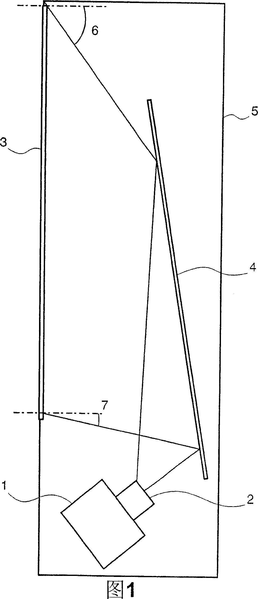
[0026] FIG. 1 is a cross-sectional view of a rear projection type image display device according to the present invention. The image source 1 is composed of a projection type cathode ray tube, a reflective or transmissive liquid crystal panel, or an image modulation element such as a display element having a plurality of micromirrors, and displays a small image. The projection lens 2 magnifies a small image displayed on a display screen of an image source, and projects it on a rear projection screen 3 . Reflecting mirror 4 is provided in the middle of the optical path from the output surface of projection lens 2 to the input surface of screen 3 . Therefore, the image enlarged by the projection lens 2 is reflected by the mirror 4 and projected onto the back of the screen 3 . Thereby, the depth of the device is reduced. These elements are housed in the casing 5 and fixed at predetermined positions. Here, in order to make the depth of the housing, for example, 300 mm or less, ...

Embodiment 2

[0045]Next, a second embodiment of the present invention will be described with reference to FIGS. 7 to 9 . Fig. 6 shows a configuration example of a direct-view image display device used in the present invention, Fig. 7(a) is a sectional view of the device viewed from above, and Fig. 7(b) is a sectional view of the device viewed from the side .

[0046] The light source 27 includes a high-pressure mercury lamp that is a substantially point light source, and a reflector that reflects and emits light emitted from the lamp. The brightness of the light emitted from the light source 27 is uniformized by the rod lens 26 . Although a method of uniformizing luminance may also utilize a multi-lens array, arbitrary elements may be used in this embodiment. The light emitted from the rod lens 26 is reflected by the reflector 25 which is a component of the projection unit, and enlarged and projected on the image generation source 21 via the Fresnel lens sheet 22 . Here, the image gener...


PUM

PropertyMeasurementUnit
angle of incidenceaaaaaaaaaa

Abstract

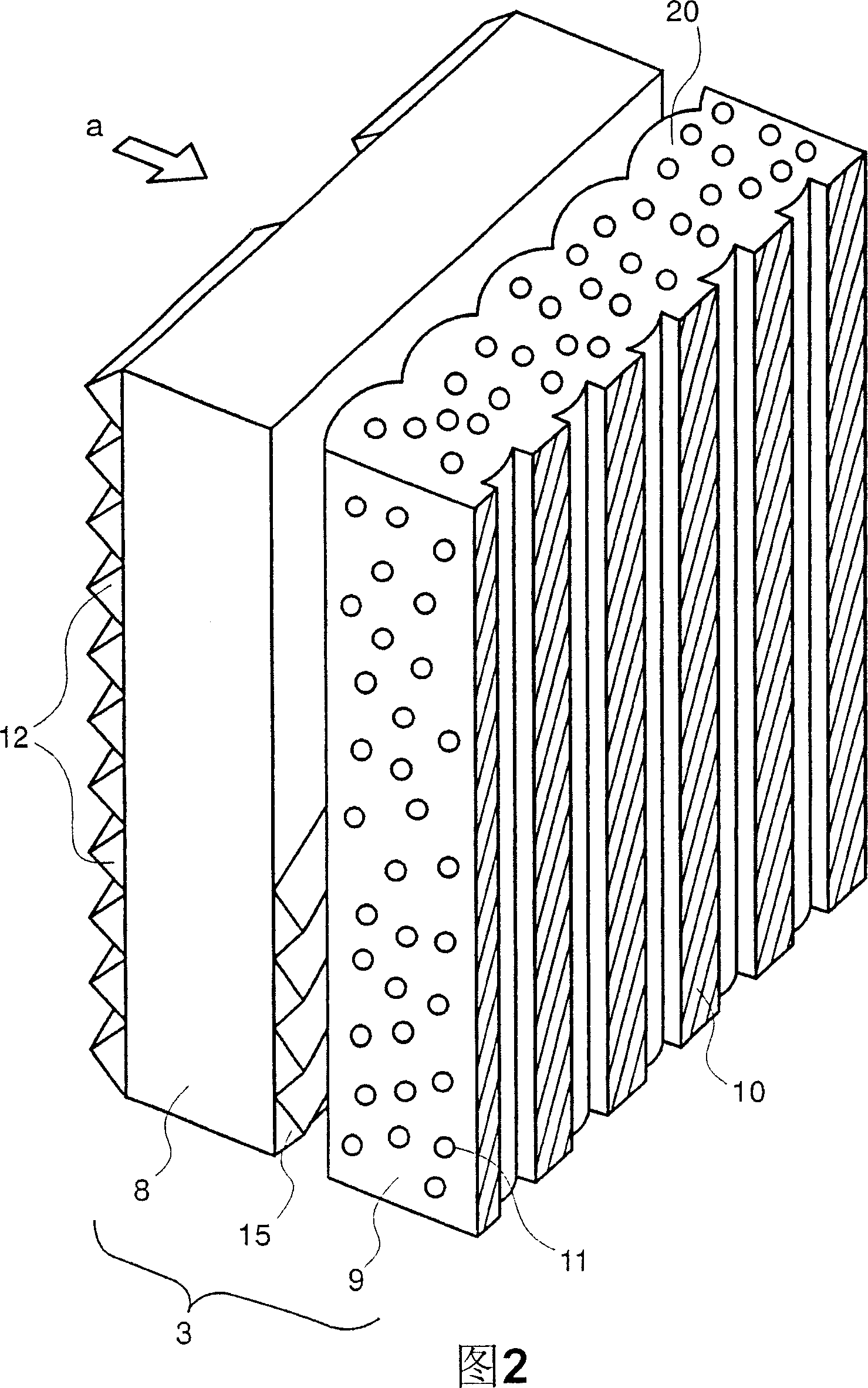
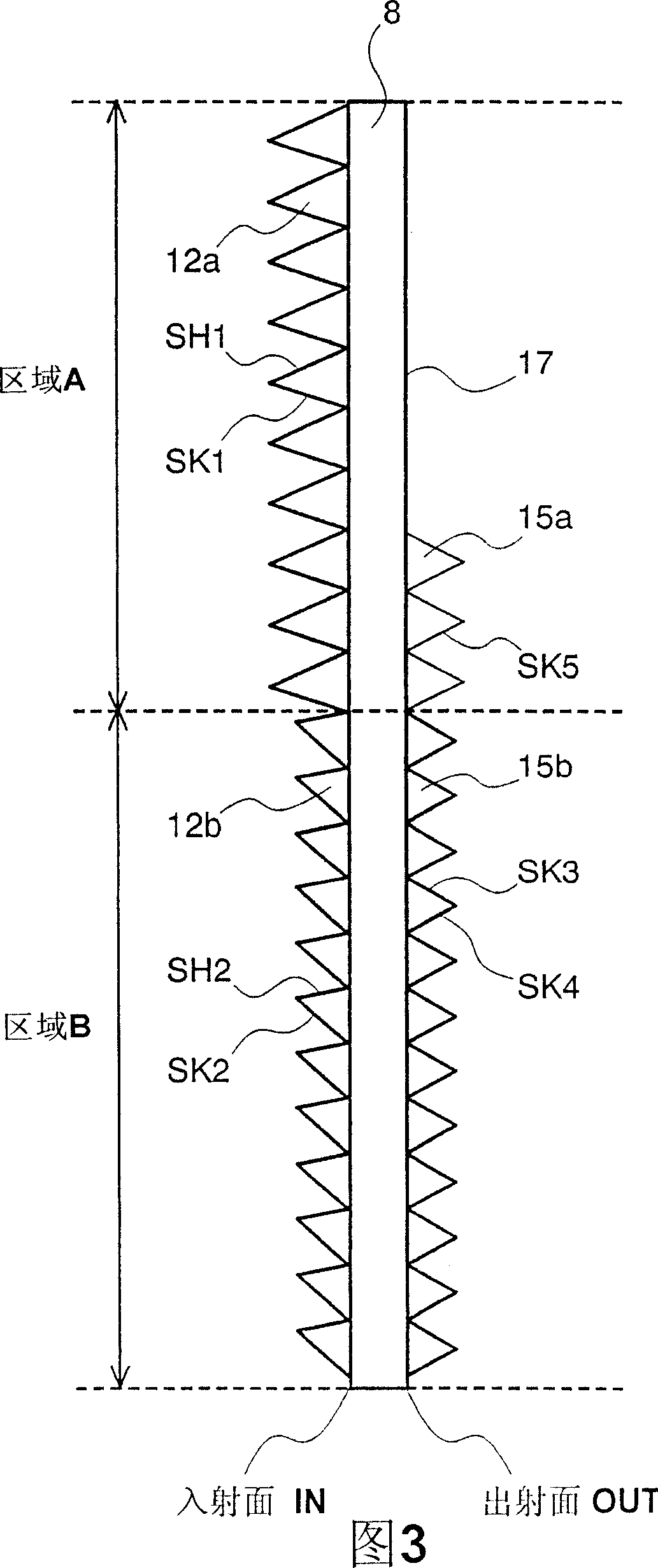
The present invention provided a technic of eliminating the brightness uneven of a projection image in a visual display unit of projecting the image light to the rear projection screen and amplifying the projection image. The Fresnel lens sheet is provided with a first prism group in an area of a light entrance plane of the Fresnel lens sheet where the incident angle of light is equal to or more than a predetermined incident angle and a second prism group in an area of a light entrance plane of the Fresnel lens sheet where the incident angle of light is less than the predetermined value. The first prism group contains the first plane of refraction which refractes the light whose incident angle is equal to or more than a predetermined incident angle, and the first complete reflective surface which reflects the light refracted by the first plane of refraction and leads the light to the emergente side of the Fresnel lens. The second prism group contains the second plane of refraction which refractes the light whose incident angle is less than the predetermined value and leads the light to the emergente side of the Fresnel lens, and the second complete reflective surface which reflects a part of light refracted by the second plane of refraction and leads the light to the emergente side of the Fresnel lens.

Description

technical field [0001] The present invention relates to a rear projection type or direct view type image display device and a Fresnel lens sheet used therein. Background technique [0002] In a rear projection type image display device (hereinafter, sometimes referred to as a device) that magnifies and projects a small video on a screen, it is desired to reduce the thickness of the device (reduce the depth dimension). If the depth dimension of the device is shortened, the incident angle of light becomes large especially at the peripheral portion of the screen. Therefore, the utilization efficiency of light decreases (that is, the reflection loss increases) at the peripheral portion of the screen, and the image becomes dark. As a prior art for coping with this, for example, what is described in Japanese Patent Application Laid-Open No. 2004-170862 is known. It is disclosed that on the light incident surface (image generation source side) of the Fresnel lens sheet as the con...

Claims


Application Information

Patent Timeline
Patent Type & Authority Applications(China)
IPC IPC(8): G02B3/08G03B21/00G02F1/13
Inventor 吉川博树久田隆纪大石哲平田浩二今福大辅
Owner HITACHI LTD
Learn More