
Double optic flat plate swing mechanism

A technology of swing mechanism and optical flat panel, which is applied in optics, optical components, instruments, etc., can solve the problem of inability to adjust the optical flat panel, and achieve the effect of compact structure and improved force strength

Inactive Publication Date: 2007-06-27
SHANGHAI INST OF OPTICS & FINE MECHANICS CHINESE ACAD OF SCI
View PDF0 Cites 0 Cited by
  • Summary
  • Abstract
  • Description
  • Claims
  • Application Information

AI Technical Summary

Problems solved by technology

Similarly, the double optical flat plate swing mechanism cannot adjust the positions of the two groups of optical flat plates in the vertical direction of the swing plane

Method used


Image

  • Double optic flat plate swing mechanism
  • Double optic flat plate swing mechanism
  • Double optic flat plate swing mechanism

Examples


Embodiment Construction

[0025] The present invention will be further described below in conjunction with the accompanying drawings and embodiments, but the protection scope of the present invention should not be limited thereby.

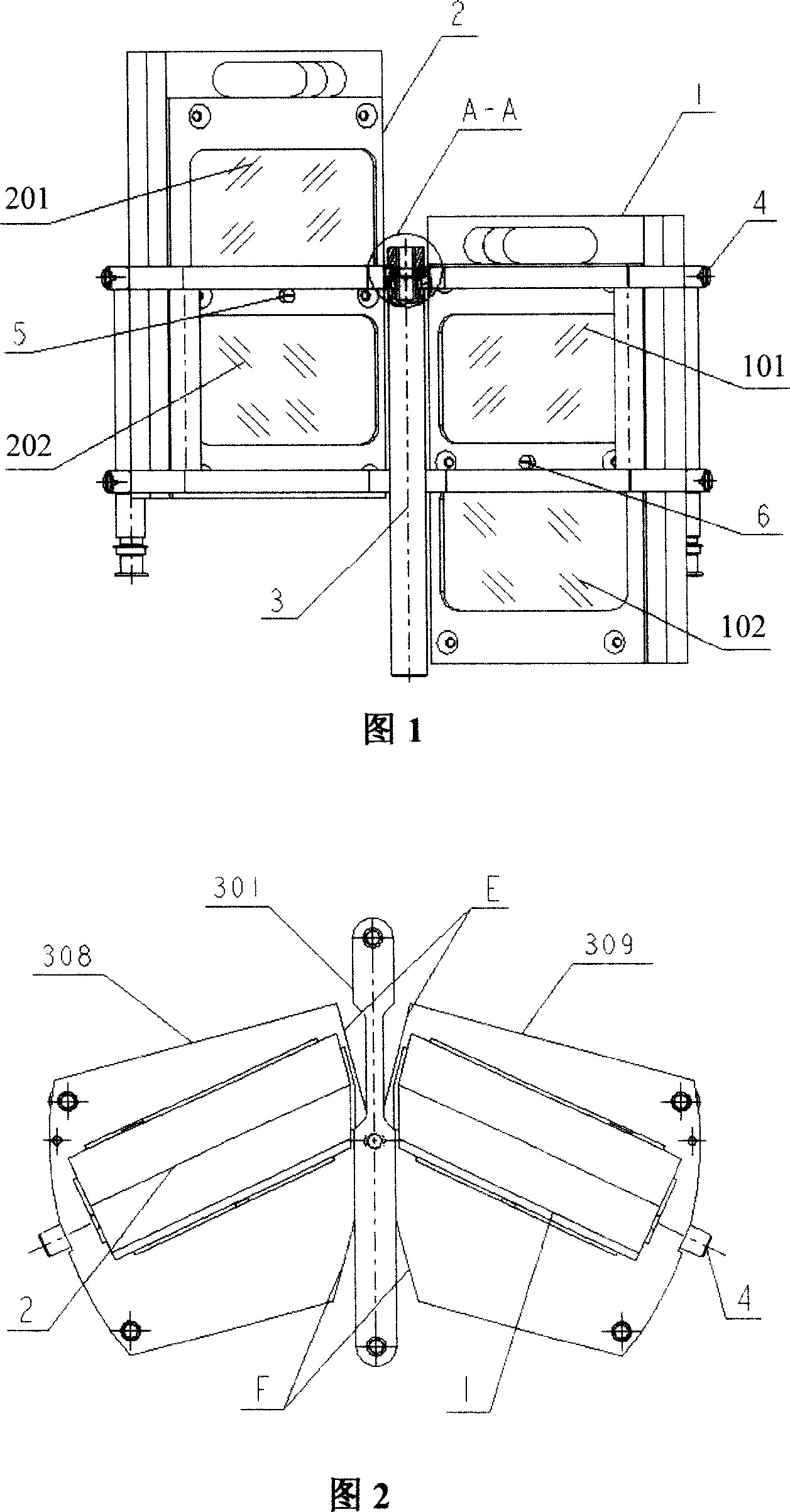
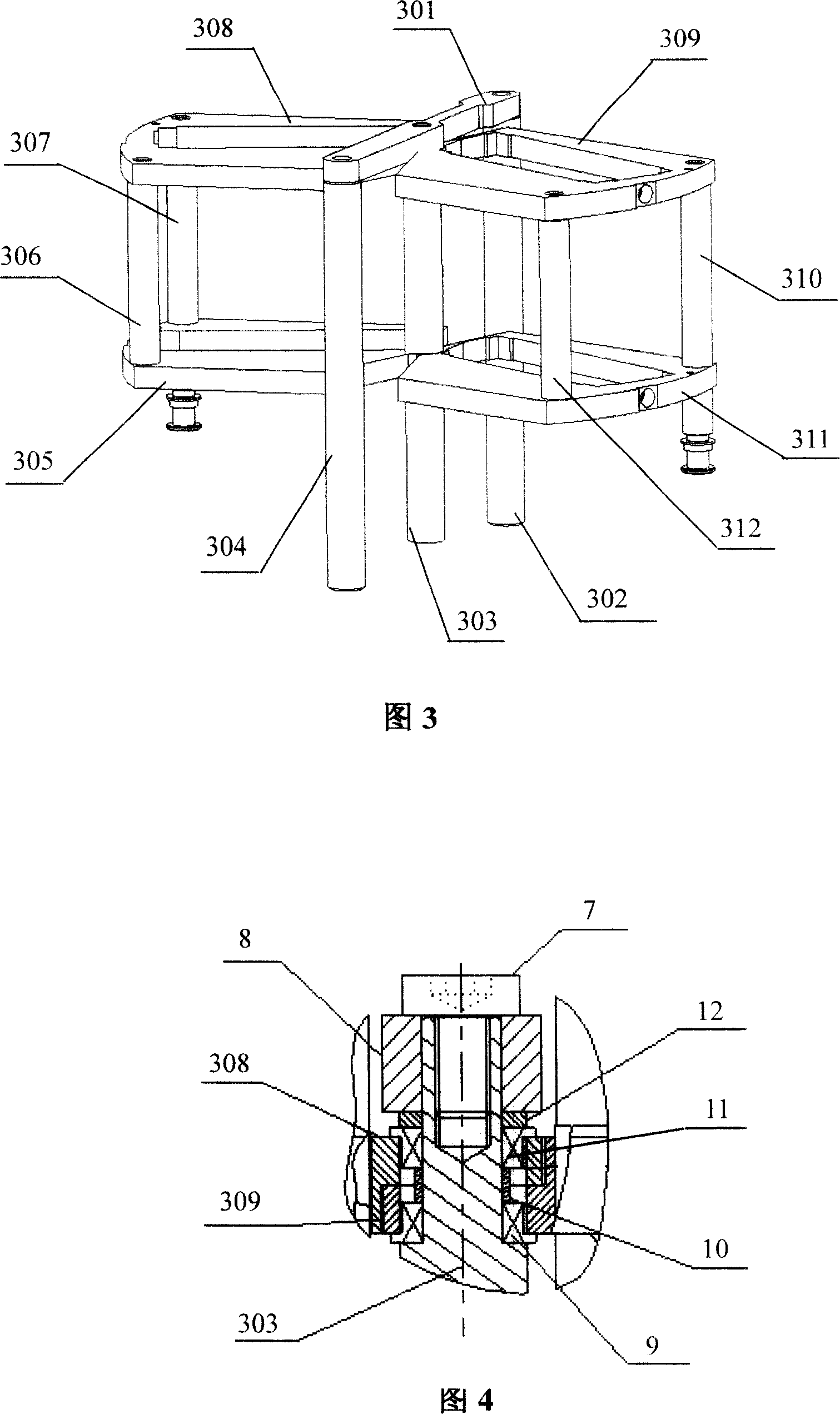
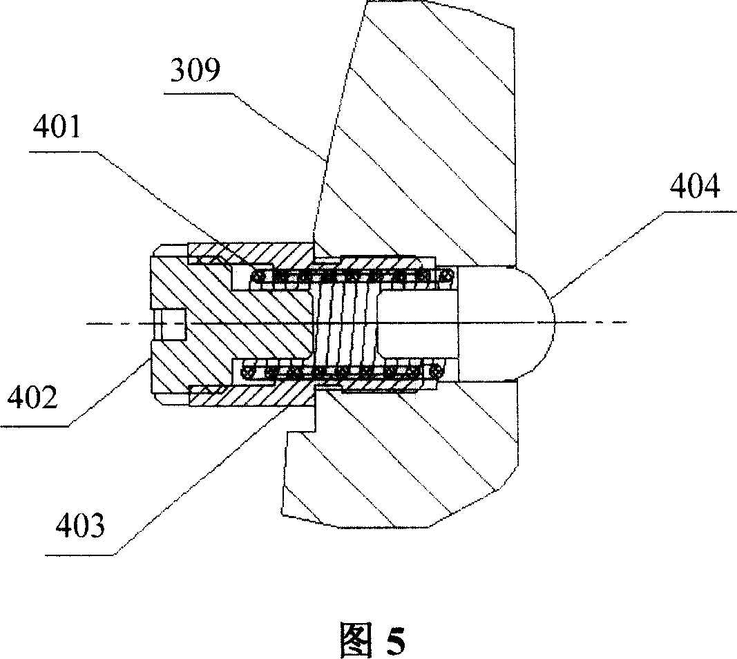
[0026] Please refer to Fig. 1, Fig. 2 and Fig. 3 first. Fig. 1 is a front view of the double optical plate swing mechanism of the present invention, which is also a front view of the structure of an embodiment of the present invention. As can be seen from the figure, the double optical plate swing mechanism of the present invention comprises a left mirror base 1, a right mirror base 2 and a support frame 3, and the support frame 3 is divided into the left and right sides of the fixed frame by a fixed frame and two structures with the same structure. Composed of a swing frame, the fixed frame includes a connecting plate 301 and a front column 304, a middle column 303 and a rear column 302, and the upper ends of the front column 304, the middle column 303 and the rear column 3...


PUM


Abstract

The swing mechanism includes mirror base, bracing frame. The bracing frame is composed of a support rack, left and right swing frames setup with same structure at two side of the support rack. The left swing frame includes two pillars, up sheet support, and low sheet support. Through two pillars, outer sides of the up and low sheet supports are connected to each other fixedly. Through up and low two bearings, the side near to the support rack connected to middle upright post. Being matched to outline size of mirror base, hole of mirror base is made in middle of the up and low sheet supports. Elastic fastening parts are setup on the up sheet support, and low sheet support. Hole of mirror base is in use for mirror base to be placed. Banking screw is setup on left and right swing frames. The invention is suitable to setting up dual optical flat in large aperture. Position control is carried out in direction perpendicular to swing plane. Features are: simple structure and compact.

Description

technical field [0001] The invention relates to a precision optical adjustment device for an optical instrument, in particular to a double optical plate swing mechanism, especially a swing mechanism suitable for adjusting the position of a large diameter double optical plate in the vertical direction of its swing plane. Background technique [0002] Optical flat plates include optical parallel flat plates and optical wedge flat plates. The double optical flat plates formed by two groups of optical flat plates are used as compensators and micrometers in optical instruments. The angle change of the double optical flat panel during use is realized by the swing mechanism, and the performance of the swing mechanism determines the use effect of the double optical flat panel. [0003] The prior art [1] (the editing group of "Optical Instrument Design Manual". Optical Instrument Design Manual. National Defense Industry Press, Beijing, 1971, P.97) provides a double optical flat plate...

Claims


Application Information

Patent Timeline
Patent Type & Authority Applications(China)
IPC IPC(8): G02B27/62G02B5/00
Inventor 王利娟栾竹孙建锋周煜刘德安刘立人
Owner SHANGHAI INST OF OPTICS & FINE MECHANICS CHINESE ACAD OF SCI
Learn More