Image display, fresnel lens and screen used thereof

An image display device, Fresnel lens technology, applied in lens, projector with built-in screen/outside screen, image communication, etc., can solve problems such as image distortion

Inactive Publication Date: 2007-06-27
HITACHT MAXELL LTD
View PDF1 Cites 9 Cited by
  • Summary
  • Abstract
  • Description
  • Claims
  • Application Information

AI Technical Summary

Problems solved by technology

Hereinafter, in some cases, this type of projection is referred to as "ob

Method used


Image

  • Image display, fresnel lens and screen used thereof
  • Image display, fresnel lens and screen used thereof
  • Image display, fresnel lens and screen used thereof

Examples


Embodiment Construction

[0024] Embodiments will be described in detail below with reference to the drawings.

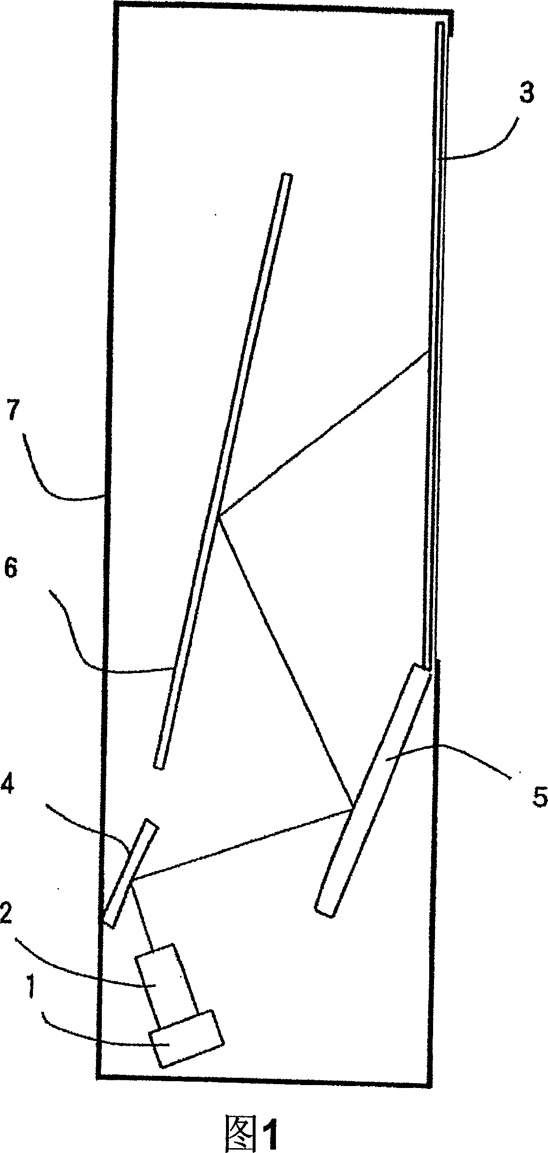
[0025] First, FIG. 1 is a cross-sectional perspective view showing an example of the structure of an image display device in this embodiment. In the figure, the image generation source 1 may be a generation source including a projection type cathode ray tube. In addition, it may be a reflective / transmissive liquid crystal panel, or a source of an image modulation element including a display element provided with a plurality of micro mirrors. When such an image modulation element is used, the image generation source further includes a light source such as a mercury lamp for irradiating light onto the image modulation element, and the image modulation element modulates the light from the light source for each pixel according to an input image signal. , thus forming an image. In this way, a small image is displayed on the display screen of the image generating source 1 . As can be seen from ...


PUM


Abstract

A projection image display unit of the present invention, projects the image from a image generation unit, passing through the projection optics which contains projector lens, curved-reflector and reflector, from the back of screen. The screen contains Fresnel lens sheet with the concentric circles shape formed in emergent surface, and the shape is aspherical while connecting to the prism face of Fresnel lens. In addition, setting a plane of incidence prism which is almost parallel to the lower end of Fresnel lens on the light incidence plane of Fresnel lens, containing the defining region opposite to the ceter of Fresnel.

Description

technical field [0001] The present invention relates to a projection type image display device using an oblique projection optical system for projecting an image of an image generating source from an oblique direction onto a rear projection type screen, and a Fresnel lens sheet and a Fresnel lens sheet used in the image display device. Rear projection type screen. Background technique [0002] In order to cope with the reduction in thickness of projection-type image display devices, there is known a configuration in which a mirror is used to project an enlarged image from an oblique direction, that is, a configuration using a so-called oblique projection optical system. At this time, since the enlarged image is obliquely projected to the screen (that is, the vertical line of the main plane of the screen and the incident direction of the light in the center of the enlarged image form a certain angle. Hereinafter, in some cases, such a projection form is called "oblique projec...

Claims


Application Information

Patent Timeline
IPC IPC(8): G03B21/60G03B21/00G02B3/08G02B17/00G03B21/10G03B21/62H04N5/74
CPCG03B21/62G02B3/08G03B21/10
Inventor 今福大辅吉川博树大石哲
Owner HITACHT MAXELL LTD
Why Eureka
Try Eureka