Back projection-type screen and back projection-type projection device
A rear projection and screen technology, which is applied to projection devices, projectors with built-in screens/external screens, optics, etc., can solve the problems of not being able to provide good images, not being able to provide images, etc.
- Summary
- Abstract
- Description
- Claims
- Application Information
AI Technical Summary
Problems solved by technology
Method used
Image
Examples
Embodiment approach 2
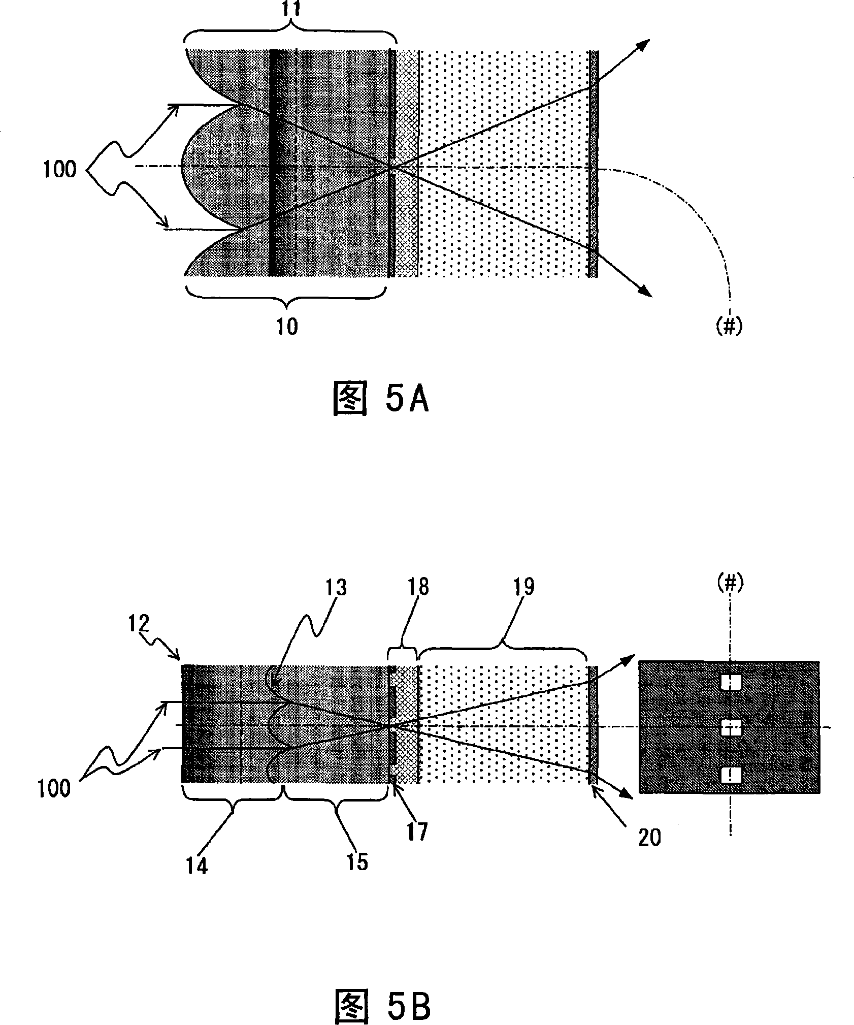
[0116] 4 is a perspective view showing the configuration of main parts of a lenticular lens sheet according to Embodiment 2 of the present invention. Below, as far as the lenticular lens sheet is concerned, the structure that does not include the self-adjusting outer light-absorbing layer 17 is a lenticular lens sheet A (marker 10 among the figures), and the self-adjusting lens sheet A is set in the lenticular lens sheet A. The sheet of the external light absorbing layer 17 is a biconvex lens sheet B (reference number 11 in the figure).
[0117] The lenticular lens sheet A is an integral lenticular lens sheet formed by the first lens layer 14 and the second lens layer 15, the first lens layer 14 and the second lens layer 15 take the second lens row 13 as a boundary surface, The refractive indices are different from each other. In Embodiment 2 of the present invention, the refractive index of the first lens layer 14 is configured to be smaller than the refractive index of the ...
Embodiment approach 3
[0172] 6 is a perspective view showing the configuration of main parts of a lenticular lens sheet according to Embodiment 3 of the present invention.
[0173] In the lenticular lens sheet A, a transparent support 21 is provided on the emission side of the second lens layer 15 . In addition, it is different from the configuration shown in Embodiment 2 of the invention in that a self-regulating external light absorbing layer 17 is provided on the surface of the transparent support 21 on the emission side. The other configurations are the same as those in Embodiment 2 of the invention, and thus, descriptions thereof are omitted.
[0174] The transparent support 21 is made of acrylic resin, MS resin, or PET film.
[0175] In the lenticular lens sheet according to Embodiment 3 of the present invention, a self-regulating external light absorbing layer 17 is formed on the exit surface side of the transparent support body 21 having the first lens row 12 and the second lens row 13 per...
Embodiment approach 4
[0185] Fig. 7 is a perspective view showing the configuration of main parts of a lenticular lens sheet according to Embodiment 4 of the present invention. In addition, in Embodiment 4, the lenticular lens sheet part formed by the first lens layer 14 and the second lens layer 15 is a lenticular lens sheet A (reference number 10 in the figure), and has a filled layer therein. 16 and the lenticular lens sheet of the self-adjusting type external light absorbing layer 17 are lenticular lens sheet B (marker 11 among the figures). In the lenticular lens sheet A, the first lens array 12 is provided on the incident surface, and the second lens array 13 is provided on the outgoing surface so as to be substantially perpendicular to the first lens array 12 . In addition, in Embodiment 4 of the present invention, a combination is formed in which the refractive index of the lens layers constituting the lenticular lens sheet A is higher than the refractive index of the filling layer 16 descr...
PUM
 Abstract
Description
Claims
Application Information
 - R&D
- Intellectual Property
- Life Sciences
- Materials
- Tech Scout
- Unparalleled Data Quality
- Higher Quality Content
- 60% Fewer Hallucinations
Browse by: Latest US Patents, China's latest patents, Technical Efficacy Thesaurus, Application Domain, Technology Topic, Popular Technical Reports.
© 2025 PatSnap. All rights reserved.Legal|Privacy policy|Modern Slavery Act Transparency Statement|Sitemap|About US| Contact US: help@patsnap.com


