Power supply

一种电源装置、负载装置的技术,应用在电路装置、电池电路装置、电路等方向,能够解决下降、燃料消耗等问题

Inactive Publication Date: 2007-06-27
PANASONIC CORP
View PDF1 Cites 8 Cited by
  • Summary
  • Abstract
  • Description
  • Claims
  • Application Information

AI Technical Summary

Problems solved by technology

On the other hand, as shown by C31, when the output current reaches A3, the supplied fuel is substantially completely consumed
Therefore, from the point of view of complete fuel combustion, it is advisable to set the operating point of the fuel cell at a point where the output current is greater than A3. Provides a stable output voltage

Method used


Image

  • Power supply
  • Power supply
  • Power supply

Examples


no. 1 Embodiment

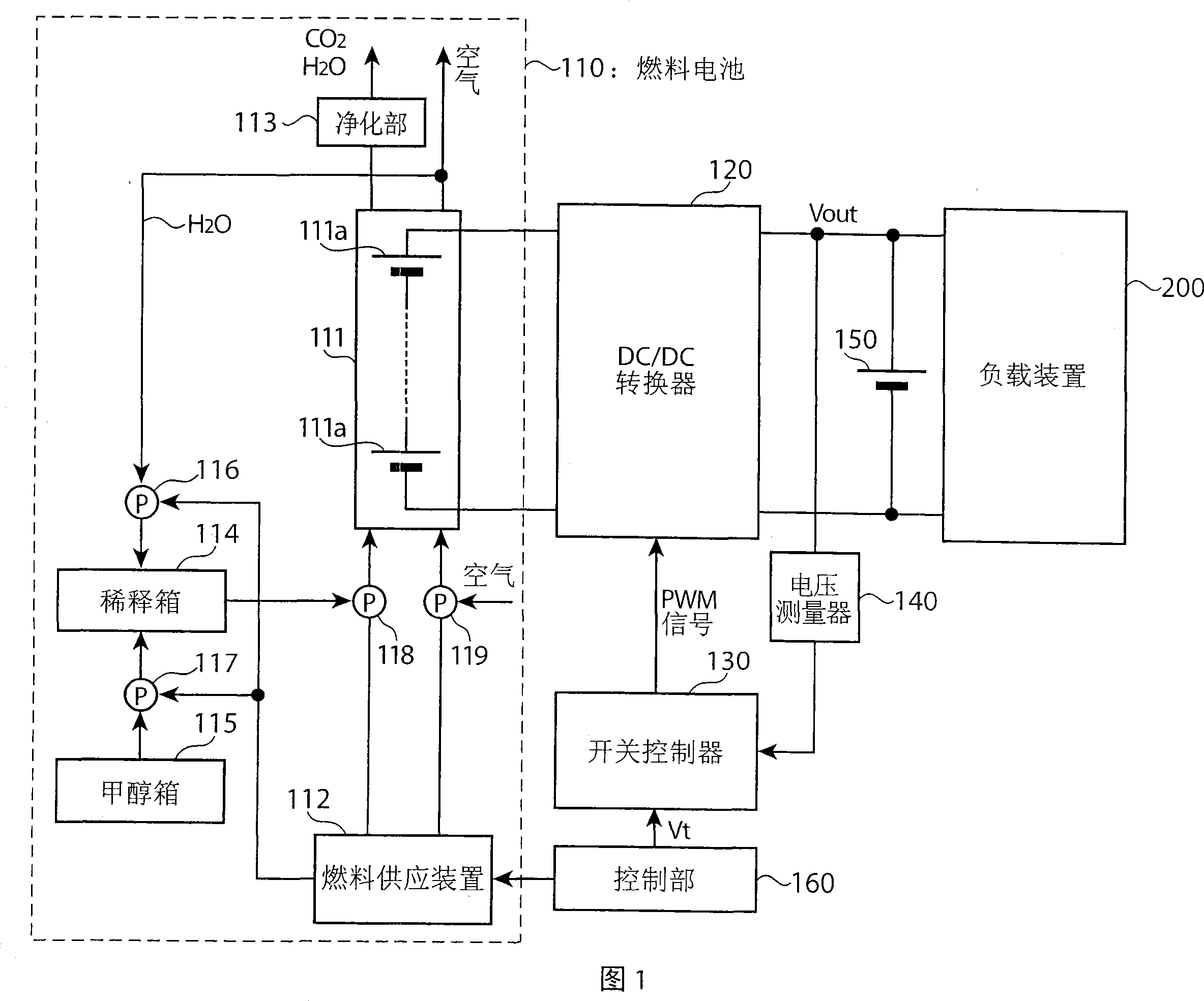
[0035] Fig. 1 is a block diagram of a power supply unit according to a first embodiment of the present invention. As shown in FIG. 1 , the power supply device includes a fuel cell 110 , a DC / DC converter 120 , a switch controller 130 , a voltage measurer 140 , a secondary battery 150 , and a control unit 160 .

[0036] The output terminal of the fuel cell 110 is connected to the input terminal of the DC / DC converter 120 . The secondary battery 150 and the load device 200 are connected in parallel to the output terminal of the DC / DC converter 120 . A voltage measuring device 140 is connected between the anode side of the output terminal of the DC / DC converter 120 and the switching controller 130 .

[0037] The fuel cell 110 is a fuel non-circulating DMFC, and includes a cell stack 111 , a fuel supply device 112 , a purification unit 113 , a dilution tank 114 , a methanol tank 115 , and pumps 116 to 119 . The fuel supply device 112 controls the pumps 116 to 119 in accordance w...

no. 2 Embodiment

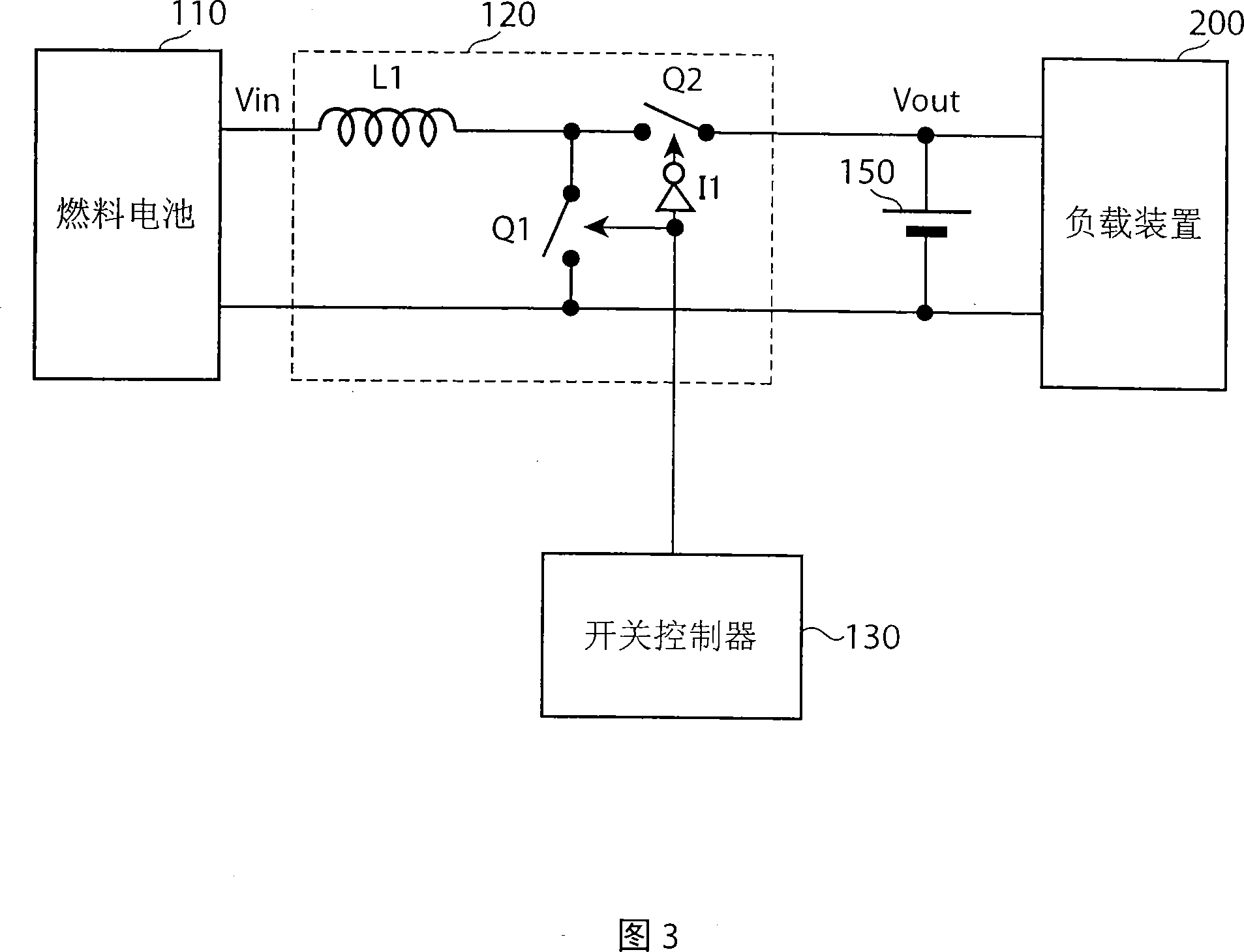
[0063]The power supply device of the second embodiment will be described below. Since the overall structure of the power supply device of the second embodiment is the same as that of the power supply device of the first embodiment, it will be described using FIG. 1 . The power supply device of the second embodiment is characterized in that a step-down (BOOST type) DC / DC converter is used as the DC / DC converter 120 in the power supply device of the first embodiment. FIG. 4 is a circuit diagram showing the configuration of a step-down DC / DC converter. The step-down DC / DC converter includes a coil L1, two switches Q1, Q2 and an inverter circuit I1. In FIG. 4, the same elements as those in FIG. 3 are denoted by the same reference numerals, and description thereof will be omitted.

[0064] The switch Q1 has one end connected to the output terminal on the anode side of the fuel cell 110, and the other end connected to the switch Q2 and the coil L1. One end of the coil L1 is conne...

no. 3 Embodiment

[0070] The power supply device of the third embodiment will be described below. The overall structure of the power supply device of the third embodiment is the same as that of the power supply device of the first embodiment, so it will be described using FIG. 1 . The power supply device of the third embodiment is characterized in that an inverter type (INVERTER type) DC / DC converter is used as the DC / DC converter 120 in the power supply device of the first embodiment. FIG. 5 is a circuit diagram showing the structure of an inverting DC / DC converter. In addition, in FIG. 5 , the same elements as those in FIG. 3 are denoted by the same reference numerals, and description thereof will be omitted. As shown in FIG. 5 , the inverter DC / DC converter includes two switches Q1 , Q2 , a coil L1 and an inverter circuit I1 .

[0071] The switch Q1 has one end connected to the anode of the fuel cell 110 and the other end connected to the coil L1 and the switch Q2. One end of the switch Q...


PUM


Abstract

There is provided a power supply in which power generation of a fuel cell can be stabilized without using the output voltage or current from the fuel cell as a negative feedback signal. The power supply comprises a fuel cell (110), a DC / DC converter (120) for delivering the output voltage from the fuel cell (110) to a load unit (200) while regulating the voltage based on a PWM signal, a switching controller (130) for generating a PWM signal being delivered to the DC / DC converter (120), a voltage measuring instrument (140) for measuring the output voltage Vout from the DC / DC converter (120), and a secondary battery (150) connected in parallel with the load unit (200). The DC / DC converter (120) calculates the duty ratio of the PWM signal by performing a predetermined operation using the voltage Vout and a target battery voltage Vt.

Description

technical field [0001] The present invention relates to a power supply device including a fuel cell. Background technique [0002] In recent years, fuel cells that can sustain power for a long time have attracted attention as power sources for electronic devices such as notebook computers and mobile phones. A variety of fuel cells have been developed, but as a power source for portable electronic devices such as notebook computers that require miniaturization, fuel cells of the type that directly supply power without reforming the fuel through a reformer, such as direct Methanol type fuel cells (direct methanol fuel cell) (hereinafter referred to as "DMFC") are expected to be high. [0003] In addition, the DMFC includes a fuel cycle type in which unused fuel cells are recovered and reused in supplied methanol, and a fuel non-cycle type in which unused methanol is not used any more. For the fuel cycle type, the operating point can be stabiliz...

Claims


Application Information

Patent Timeline
Patent Type & Authority Applications(China)
IPC IPC(8): H01M8/04H01M8/00G05F1/67H01M8/10
CPCH02J7/34H01M8/1011Y02E60/523H01M8/0494Y02E60/50H01M8/0662H01M8/04559H01M8/04186H01M8/04992G05F1/67H01M8/00H01M8/10
Inventor 高田雅弘市濑俊彦高津克巳岛本健
Owner PANASONIC CORP
Why Eureka
Try Eureka