V-shape belt-type automatic transmission

A technology of automatic transmission and variable speed belt, applied in the direction of automatic clutch, clutch, transmission, etc., can solve problems such as large vibration, and achieve the effect of reducing vibration, increasing vibration period, and reducing adverse effects

Inactive Publication Date: 2007-07-04
YAMADA SEISAKUSHO KK
View PDF1 Cites 3 Cited by
  • Summary
  • Abstract
  • Description
  • Claims
  • Application Information

AI Technical Summary

Problems solved by technology

This causes a large vibration

Method used


Image

  • V-shape belt-type automatic transmission
  • V-shape belt-type automatic transmission
  • V-shape belt-type automatic transmission

Examples


Embodiment Construction

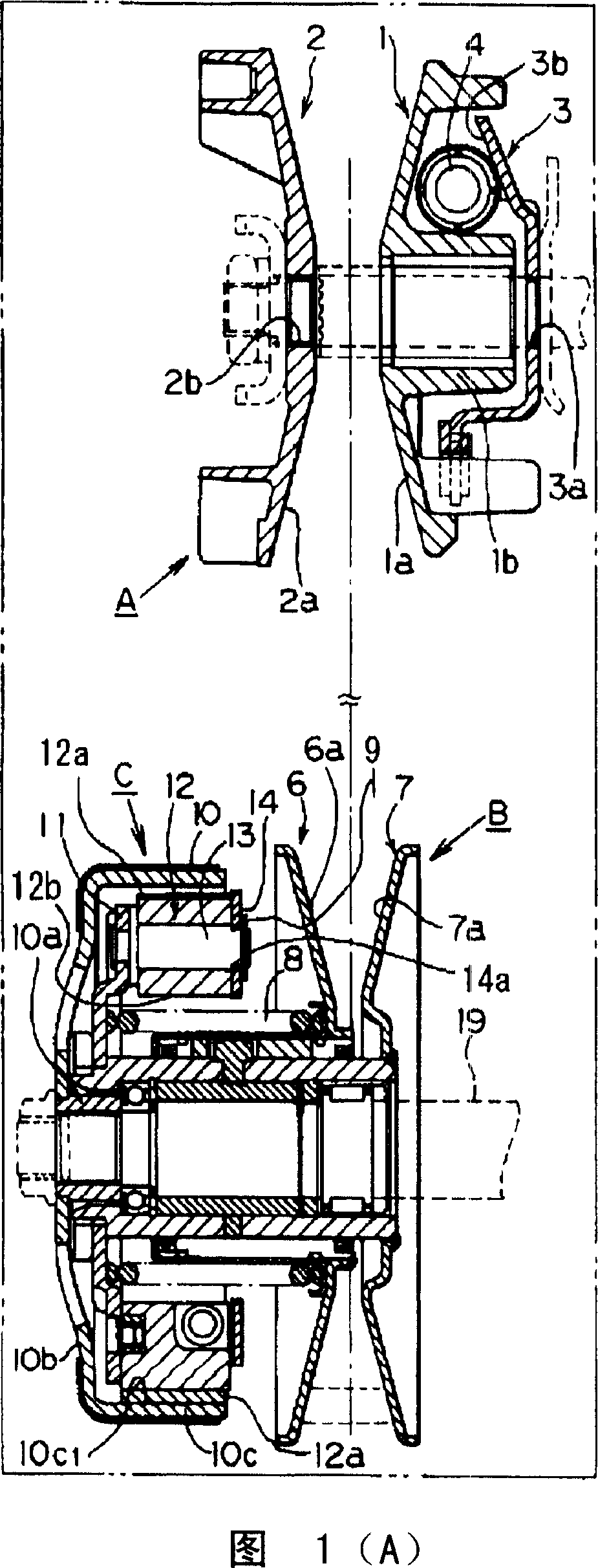
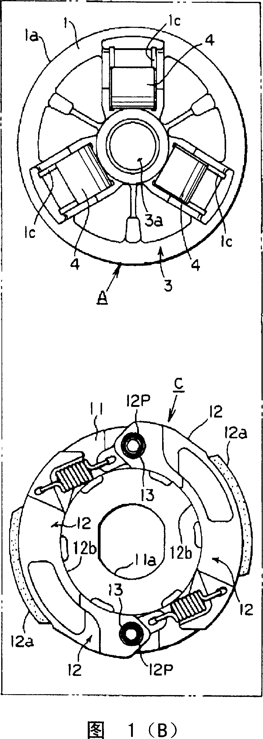
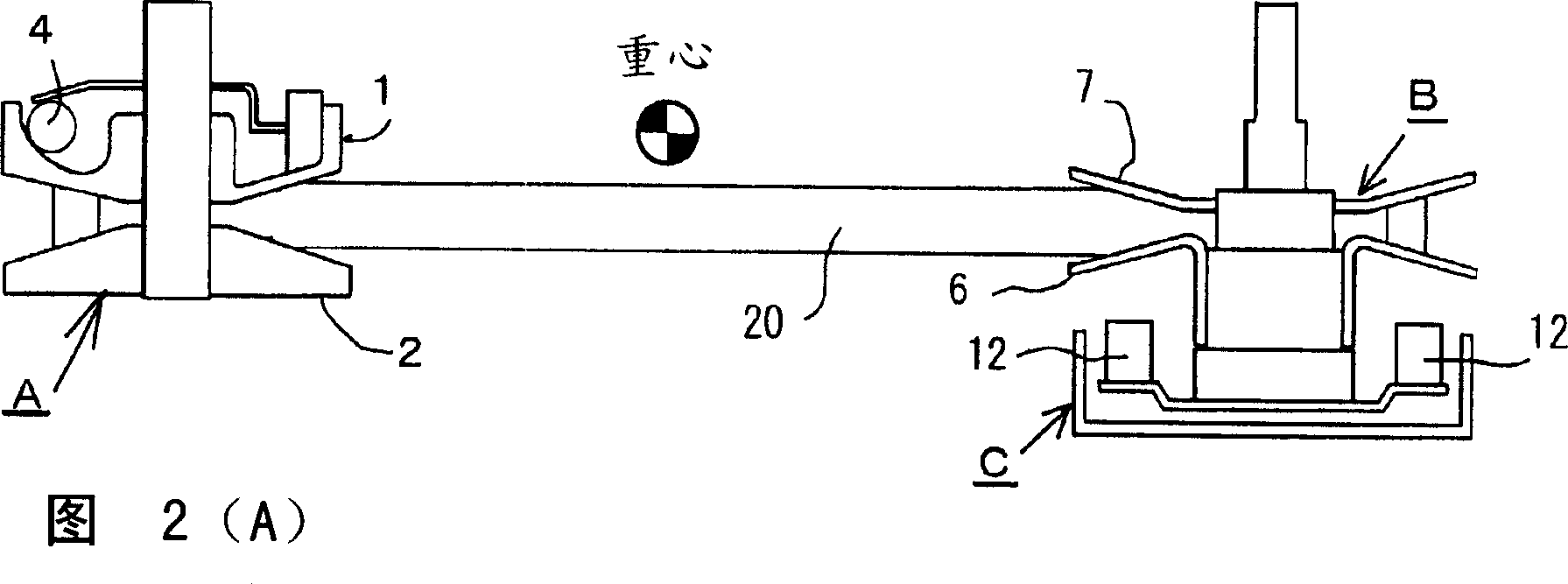
[0026] Hereinafter, embodiments of the present invention will be described based on the drawings. First of all, the structure of the device of the present invention is shown in Figures 1, 2 and so on. It is mainly composed of a driving side speed change pulley A, a driven side speed change pulley B, and a centrifugal clutch C. On this basis, an engine is added. As an engine assembly. The drive side speed change pulley A is mounted on the crankshaft on the engine side via the drive shaft. The drive-side variable speed pulley A is mainly composed of a movable pulley half 1, a fixed pulley half 2, and a centrifugal roller 4. The movable pulley half body 1 and the fixed pulley half body 2 are opposed to each other to form a set of pulleys. The movable pulley half 1 is formed of a substantially flat conical belt abutment plate 1a and a hub 1b, and the fixed pulley half 2 is also formed of a generally flat conical belt abutment plate 2a and a hub 2b.

[0027]The belt contact plate 1a an...


PUM


Abstract

The object of the present invention is to provide a V-shaped transmission mechanism that can reduce the vibration caused by the resonance of both pulleys and has good durability in an automatic transmission mechanism composed of a variable drive side speed change pulley and a driven side speed change pulley. Belt automatic transmission. The V-belt automatic transmission of the present invention consists of a drive side speed change pulley (A) with a centrifugal roller (4) inside, a driven side speed change pulley (B), and the driven side speed change pulley (B) A centrifugal clutch (C) connected and equipped with a centrifugal hammer (12) is formed. Among the number of centrifugal rollers (4) arranged on the driving side speed change pulley (A) and the number of centrifugal hammers (12) arranged on the aforementioned centrifugal clutch (C), the larger number is relative to the smaller one The scale of numbers is non-integer.

Description

Technical field [0001] The present invention relates to a V-belt type automatic transmission, which is composed of a variable drive-side speed-change pulley and a driven-side speed-change pulley, which can reduce the vibration caused by the resonance of the two pulleys and has good durability. Background technique [0002] The ratio of the set number between the centrifugal roller arranged in the movable wheel of the driving (or driving) side speed change pulley in the V-belt automatic transmission and the centrifugal hammer of the centrifugal clutch arranged on the driven side speed change pulley (drive The number of centrifugal rollers of the side speed change pulley / the number of centrifugal hammers of the driven side speed change pulley) is generally an integer value. Such a structure in which the aforementioned ratio is set to an integer value is common in the prior art. For example, it has been disclosed in many documents such as Patent Document 1 below. In the case of this...

Claims


Application Information

Patent Timeline
Patent Type & Authority Applications(China)
IPC IPC(8): F16H9/18
CPCF16D43/18F16D2043/145
Inventor 川岛芳德渡边学道木正之
Owner YAMADA SEISAKUSHO KK
Why Eureka
Try Eureka