
Liquid crystal display device

A liquid crystal display and device technology, applied to LCD. field, able to solve problems such as LCD panel 2 failure

Active Publication Date: 2007-07-04
LG DISPLAY CO LTD
View PDF0 Cites 8 Cited by
  • Summary
  • Abstract
  • Description
  • Claims
  • Application Information

AI Technical Summary

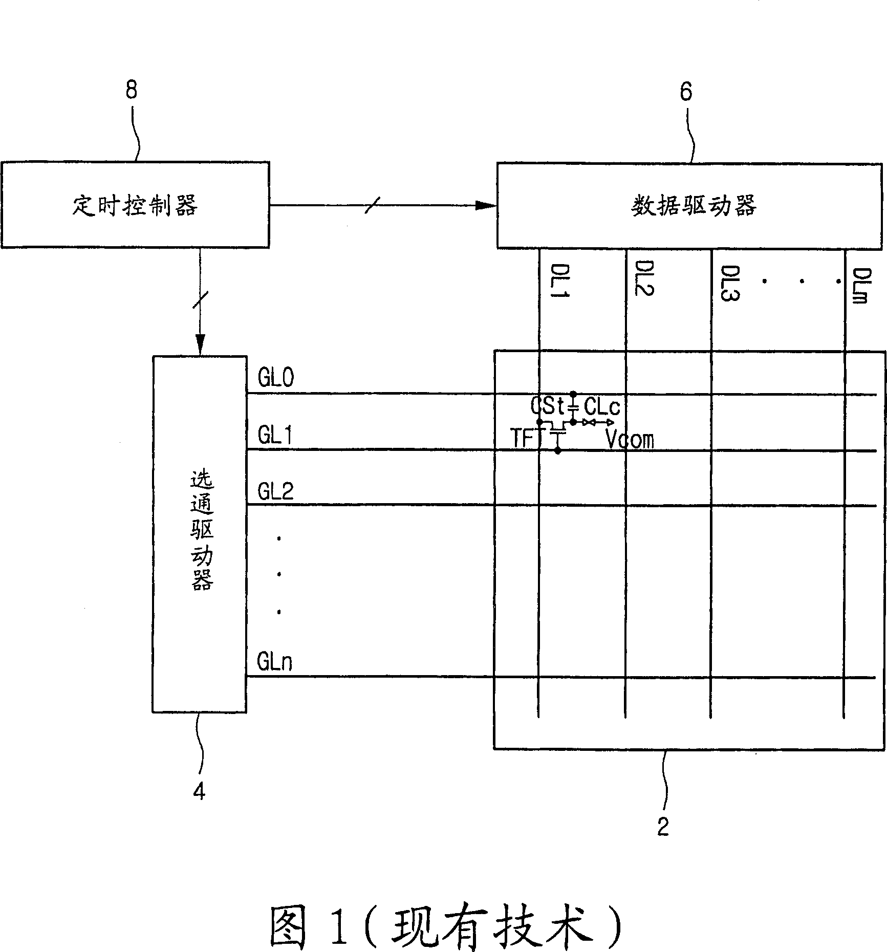
Problems solved by technology

Therefore, failure of the liquid crystal panel 2 may occur due to heat generation effect

Method used


Image

  • Liquid crystal display device
  • Liquid crystal display device
  • Liquid crystal display device

Examples


Embodiment Construction

[0027] Exemplary embodiments may be better understood with reference to the accompanying drawings, but these examples are not limiting. Wherever possible, the same reference numbers will be used throughout the drawings to refer to the same or like parts.

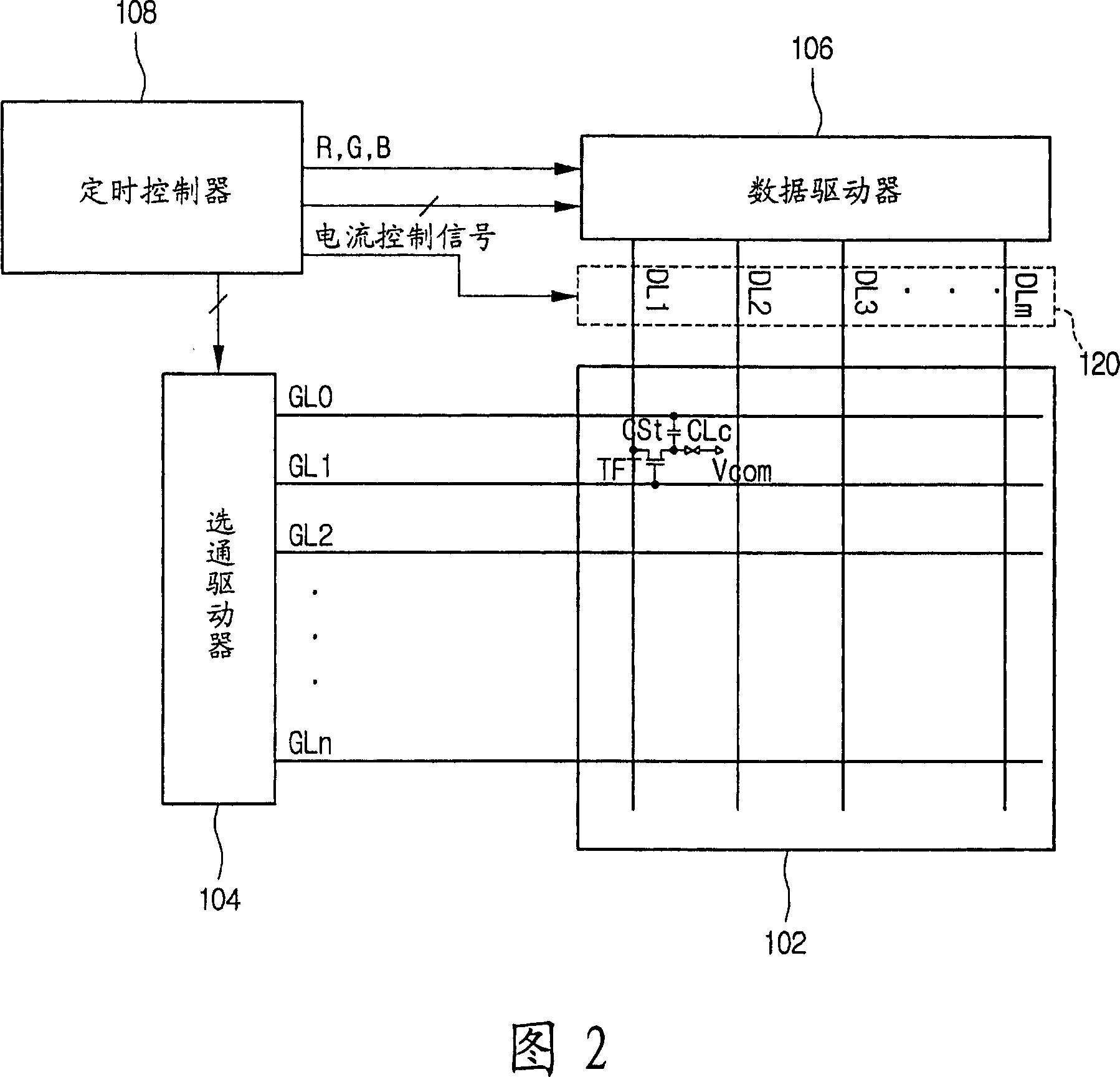
[0028] Fig. 2 shows an embodiment, wherein the LCD includes: a liquid crystal panel 102 for displaying images, which includes a plurality of gate lines GL0 to GLn and data lines DL1 to DLm; a gate driver 104 for GL0 to GLn; a ​​data driver 106 for driving the plurality of data lines DL1 to DLm; and a timing controller 108 for controlling the gate driver 104 and the data driver 106 .

[0029] A plurality of thin film transistors (TFTs) are formed at intersections of the gate lines GL0 to GLn and the data lines DL1 to DLm on the liquid crystal panel 102 . These TFTs are connected to pixel electrodes (not shown) overlapping the gate lines GL0 to GLn to form capacitors Cst.

[0030] The gate driver 104 supplies scan signals (i...


PUM


Abstract

Providing a liquid crystal display device. Describing a LCD having reduced power consumption. The LCD comprises: a liquid crystal panel, having a plurality of gating lines and data lines; a data driver used for supplying data voltage to the data lines; a controller generating current control signal to control the output terminal of the data driver, for making the output terminal operate during the first time quantum of outputting data from the data driver, and do not operate during the second time quantum of outputting no data from the data driver; and a gating driver, used for supplying scanning signals to the gating lines.

Description

technical field [0001] The present invention relates to a liquid crystal display device (LCD), and more particularly, to an LCD capable of reducing power consumption. Background technique [0002] A liquid crystal display (LCD) using an active matrix driving method can display moving images using thin film transistors (TFTs) serving as switching elements. LCDs are widely used in computers (eg, personal computers and notebook computers, etc.), office automation equipment (copiers, etc.), and portable devices (eg, mobile phones, pagers, etc.) because of their thinness and lightness. [0003] The liquid crystal panel includes a plurality of pixels arranged in a matrix, and a plurality of TFTs for switching data signals to be applied to the respective pixels. Images are displayed on the screen while the liquid crystal panel controls the amount of transmitted light provided from the backlight. [0004] The LCD includes a liquid crystal panel for displaying images and a driving ...

Claims


Application Information

Patent Timeline
IPC IPC(8): G02F1/133G09G3/36
CPCG09G2330/021G09G3/3688G09G2310/0248G02F1/133
Inventor 张喆相崔晋喆
Owner LG DISPLAY CO LTD
Learn More