Vibration motor

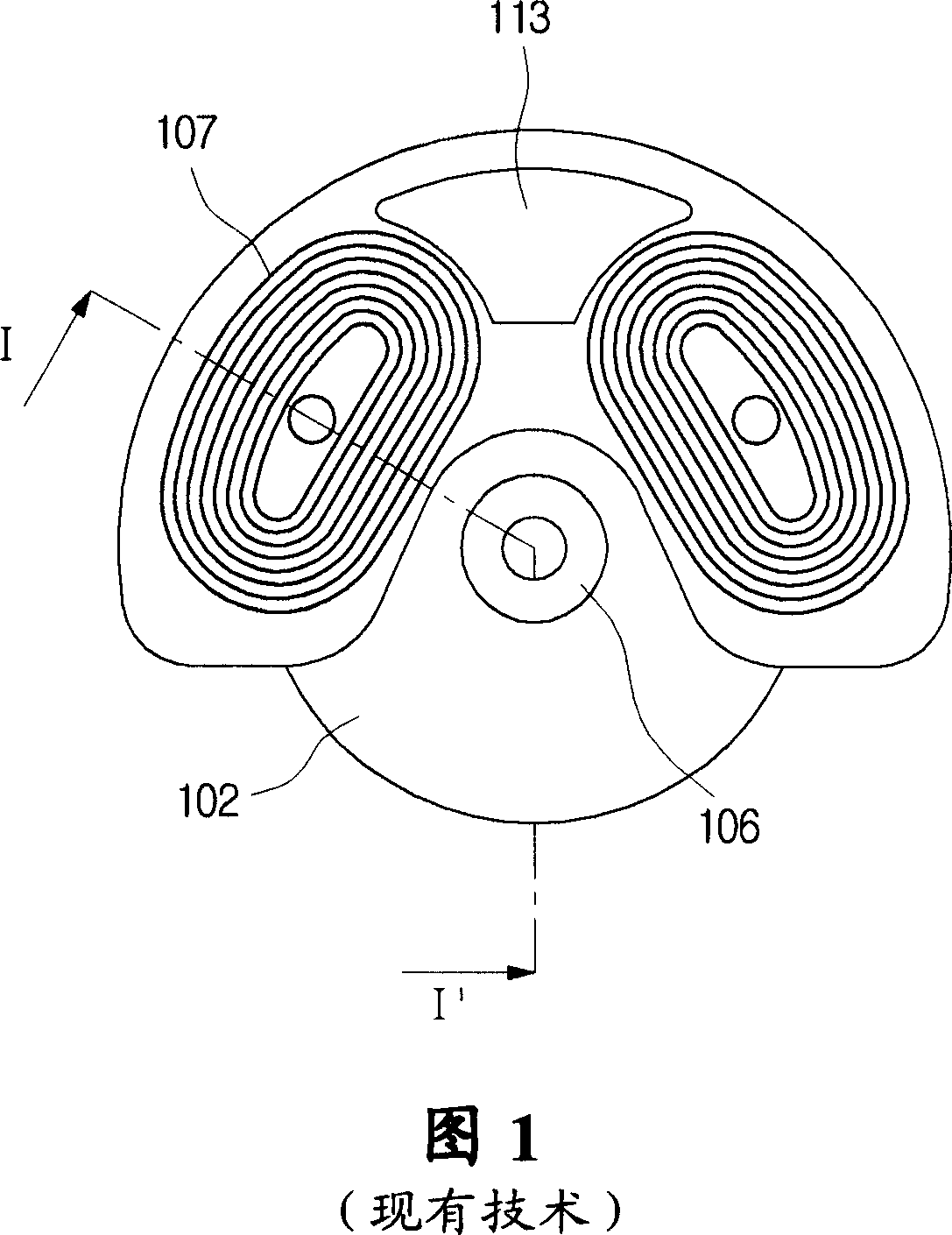
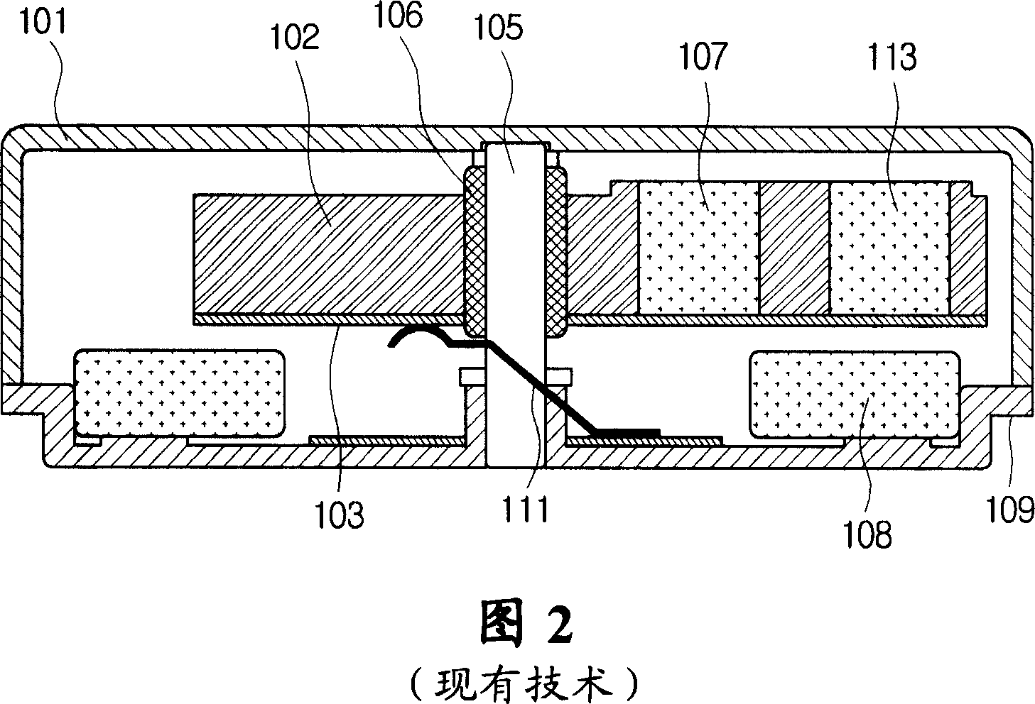
A technology for vibrating motors and bases, which is applied in the manufacture of motor generators, fluids and electrical components using vibration, etc., can solve the problems of insufficient number of magnetic lines of force, intensified motor vibration, and inability to increase the size of coil 107.

Inactive Publication Date: 2007-07-04
SAMSUNG ELECTRO MECHANICS CO LTD
View PDF0 Cites 3 Cited by
  • Summary
  • Abstract
  • Description
  • Claims
  • Application Information

AI Technical Summary

Problems solved by technology

[0010] However, as shown in FIG. 1, in the conventional coin-type vibration motor, since the counterweight 113 is positioned on the upper part of the rotor, the size of the coil 107 cannot be increased, and thus the vibration of the motor cannot be enhanced.
In addition, since the magnet 108 is mounted only on the bracket 109, the number of flux lines passing through the coil 107 cannot be large enough, so that the vibration of the motor cannot be enhanced.

Method used


Image

  • Vibration motor
  • Vibration motor
  • Vibration motor

Examples


Embodiment Construction

[0021] Hereinafter, embodiments of the present invention will be described more specifically with reference to the accompanying drawings. In the description with reference to the drawings, those same or corresponding components are provided with the same reference numerals regardless of the drawing numerals, and redundant explanations are omitted.

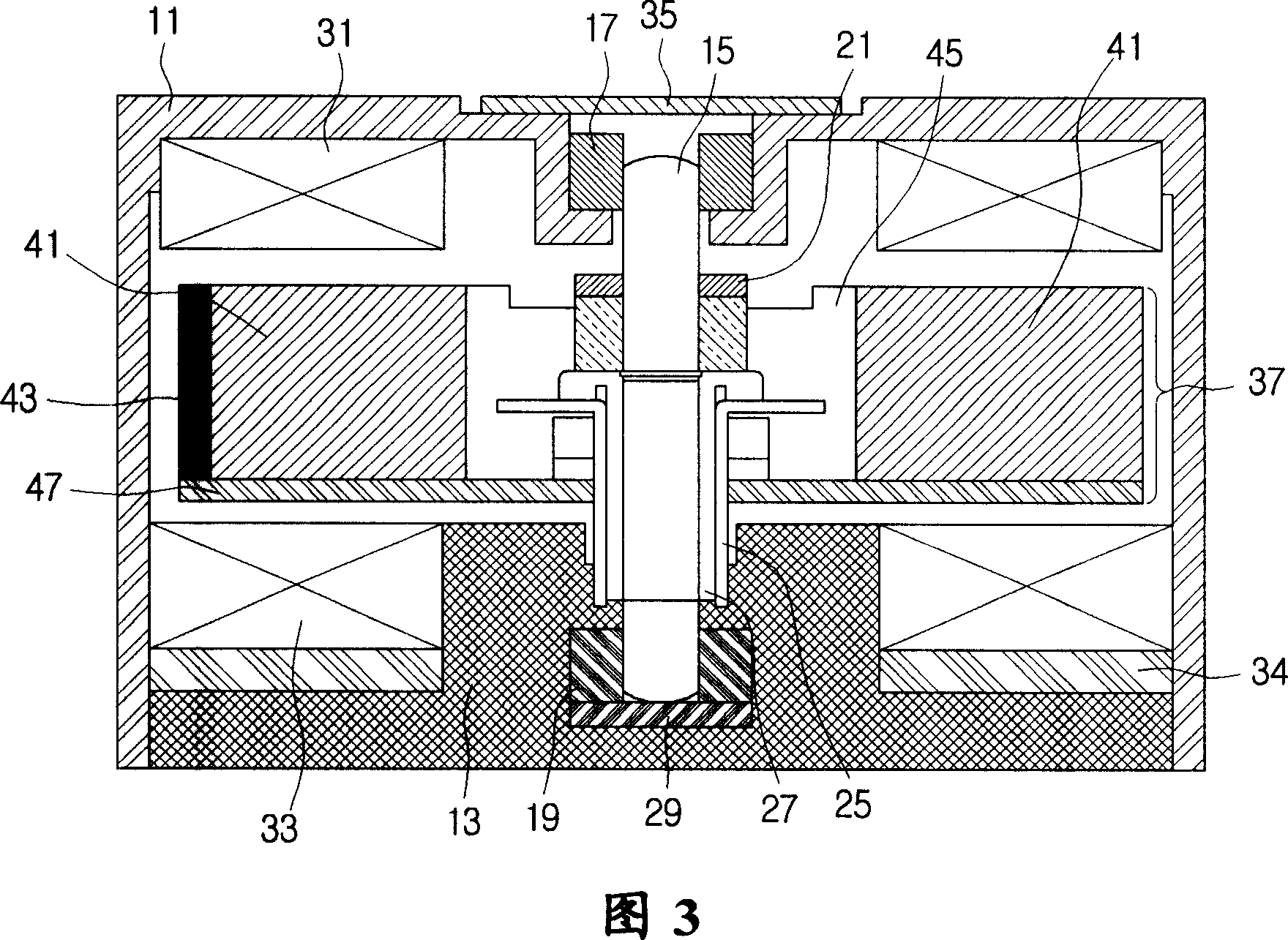
[0022] With reference to Fig. 3, the vibrating motor according to the embodiment of the present invention comprises: base 13 and housing 11, and it forms inner space; Shaft 15, is rotatably inserted in base 13 and housing 11; support and cause vibration; the counterweight 43 is installed along the periphery of the rotor 37; the brush 25 is in contact with the commutator 27 and is positioned on the base 13; and the upper magnet 31 and the lower magnet 33 face the rotor 37 and are respectively fixed to the housing 11 and the base 13. The rotor 37 includes a wound coil 41 and a counterweight 43 which may be fixed to a hard board 47 b...


PUM


Abstract

A vibration motor is disclosed. A vibration motor that includes a base and a case which form an internal space, a shaft rotatably inserted in the base and the case, a rotor inserted onto the shaft and configured to rotate, which includes multiple wound coils and a commutator connected to the wound coils, a weight arranged along the periphery of the rotor, a brush which is in contact with the commutator and which is positioned on the base, and an upper magnet and a lower magnet which face the rotor and which are secured respectively to the case and the base, can not only increase vibration but can also reduce electrical consumption.

Description

[0001] Related Application Cross Reference [0002] This application claims the benefit of Korean Patent Application No. 2005-0130579 filed with the Korean Intellectual Property Office on December 27, 2005, the entire contents of which are hereby incorporated by reference. technical field [0003] The invention relates to a vibration motor. Background technique [0004] In general, a vibration motor generates vibration when a rotor rotates in an eccentric structure, and such a vibration motor is generally manufactured to have a small size for use in a mobile phone or a pager or the like. [0005] Fig. 1 and Fig. 2 have shown common coin-type vibration motor, and wherein Fig. 1 is the plane view of rotor molding part (mold portion), and this rotor molding part is integrated with the rotor that is arranged on the inner side upper part of vibration motor, and Fig. 2 is a cross-sectional view specifically showing the coin-type vibration motor along the section II' of FIG. 1 . ...

Claims


Application Information

Patent Timeline
Patent Type & Authority Applications(China)
IPC IPC(8): H02K7/065H02K23/00H02K23/04H02K23/26H02K5/02
CPCH02K23/54H02K7/063H02K5/1672B06B1/045H02K5/14H02K15/03
Inventor 奇铉胜
Owner SAMSUNG ELECTRO MECHANICS CO LTD
Why Eureka
Try Eureka