Temperature indicating controller for use in transformer

A technology for transformers and controllers, which is applied in the field of temperature indicating controllers for transformers, and can solve the problems of large instrument volume and large measurement errors

Inactive Publication Date: 2007-07-11
王世有
View PDF0 Cites 6 Cited by
  • Summary
  • Abstract
  • Description
  • Claims
  • Application Information

AI Technical Summary

Problems solved by technology

[0003] The purpose of the present invention is to solve the technical problems of large instrument volume and large measurement error existing in the prior art, and provide a temperature indicating controller for transformers with small volume, high sensitivity, convenient adjustment, and full range setting of temperature control points.

Method used


Image

  • Temperature indicating controller for use in transformer
  • Temperature indicating controller for use in transformer

Examples


Embodiment Construction

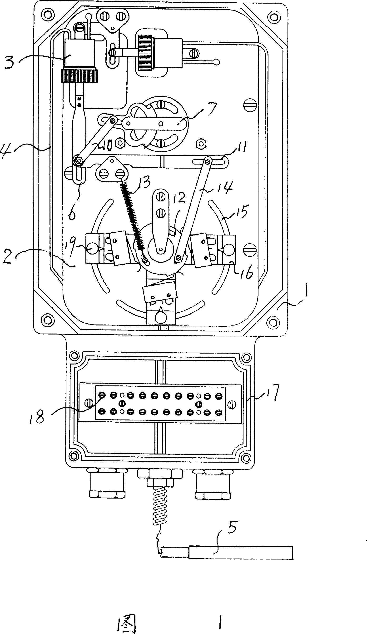
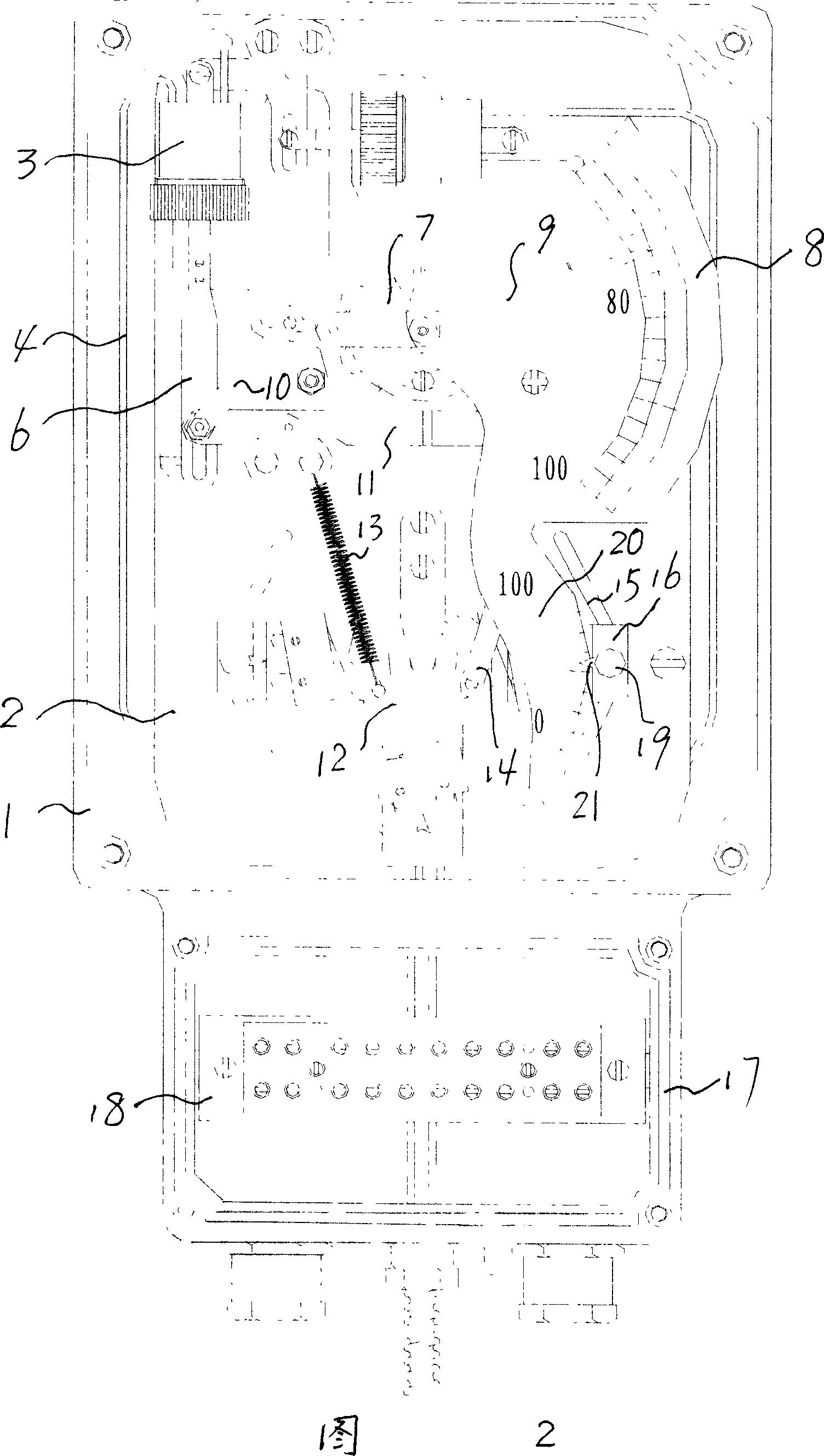
[0011] The specific embodiment of the present invention will be described below in conjunction with accompanying drawing: a kind of temperature indicator controller for transformer as shown in Figure 1, 2, same as prior art, has casing 1, and base 2 is set in casing 1, and base 2 is fixed with an elastic element 3, and a sensing conduit 4 is connected to the elastic element 3, and the other end of the sensing conduit 4 is connected with a temperature-sensing component 5 placed outside the housing 1; Rod 6, the push rod 6 drives the movement 7, and the movement 7 is connected with a pointer 9 placed on the instrument panel 8. What is different from the prior art is that the elastic element 3 and the push rod 6 connected thereto are vertically arranged, and a pull rod 10 is connected between the push rod 6 and the movement 7, and the connection between the pull rod 10 and the movement 7 Fixed by pins. Also connected with push rod 6 is transverse lever 11, also be fixed with cam...


PUM


Abstract

The temperature indicating controller for transformer sets an inlaid base of the shell fixed with vertical set elastic components that connected with vertical set catch bar which drives the machine core, brace between the catch bar and the machine core, horizontal lever connected with the catch bar, cam fixed on the base at the bottom of the horizontal lever, an extension spring fixed with one end of the supporting point of the horizontal lever and connected with the cam, cam brace fixed on the other end of the horizontal lever, ring groove centered with the cam on the base with switch components that may contact with the cam on the ring groove. It is small in size, flexible, convenient in adjustment; with all the way set temperature control point.

Description

Technical field: [0001] The invention relates to a thermometer for transformers, in particular to a temperature indicating controller for transformers with simple structure and high precision, which can measure and control the temperature of transformer oil surface and windings and can set the temperature control point in full range. Background technique: [0002] The thermometer for transformers includes a thermometer for measuring the oil level of the transformer and a thermometer for measuring the sum of the temperature of the transformer winding and the oil surface. The elastic element is mainly installed in the casing, and a sensing conduit is connected to the elastic element. The other end of the sensing conduit is connected to There are temperature-sensitive components (temperature bulbs). The sealed system composed of elastic elements, sensing conduits and temperature-sensing components is filled with temperature-sensing medium. When the temperature of the measured (...

Claims


Application Information

Patent Timeline
Patent Type & Authority Applications(China)
IPC IPC(8): G05D23/02H01F27/00
Inventor 王世有
Owner 王世有
Why Eureka
Try Eureka