Dual voltage electrical body nano positioning and voltage electrical driver, its control method and controller

A piezoelectric driver, nano-positioning technology, applied in piezoelectric devices/electrostrictive devices, generators/motors, piezoelectric effect/electrostrictive or magnetostrictive motors, etc. Temperature zone, small volume, easy integration and other issues, to achieve the effect of simple structure, large working temperature zone, and easy integration

Inactive Publication Date: 2007-07-11
UNIV OF SCI & TECH OF CHINA
View PDF3 Cites 19 Cited by
  • Summary
  • Abstract
  • Description
  • Claims
  • Application Information

AI Technical Summary

Problems solved by technology

[0007] In order to avoid the shortcomings of the above-mentioned prior art, the present invention provides a dual piezoelectric body linear nano-positioning piezoelectric driver, its control method and controller, by adopting only two piezoelectric actuators and rationally utilizing Friction, to overcome the shortcomings of existing piezoelectric motors that cannot simultaneously have important performances such as large working temperature range, two-way large-range travel, strong thrust, nanometer positioning accuracy, small size, easy integration, and low cost

Method used


Image

  • Dual voltage electrical body nano positioning and voltage electrical driver, its control method and controller
  • Dual voltage electrical body nano positioning and voltage electrical driver, its control method and controller
  • Dual voltage electrical body nano positioning and voltage electrical driver, its control method and controller

Examples


Embodiment 1

[0065] Example 1: Basic dual piezoelectric linear nanopositioning piezoelectric actuator

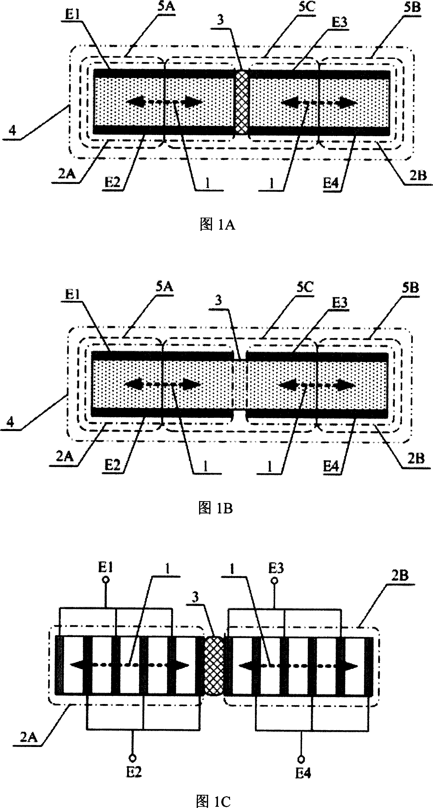
[0066] Referring to Fig. 1A, the left and right piezoelectric actuators are fixedly connected to the connecting body 3 in a mechanically in series manner along the deformation direction 1 to form independently controllable two-connected bodies 4; or as shown in Fig. 1B: The electrodes of a piezoelectric actuator are divided into two to form two components respectively called the left piezoelectric actuator 2A and the right piezoelectric actuator 2B, which deform along the original deformation direction 1 and are integrated with the connecting body 3 The piezoelectric actuator constitutes a dijoint 4. The deformation refers to piezoelectric deformation.

[0067] As shown in Figures 1A and 1B, the left piezoelectric actuator 2A and the right piezoelectric actuator 2B are bounded by their respective mid-sections along their deformation directions, dividing the two conjoined bodies into thr...

Embodiment 2

[0087] Embodiment 2: force body type driver

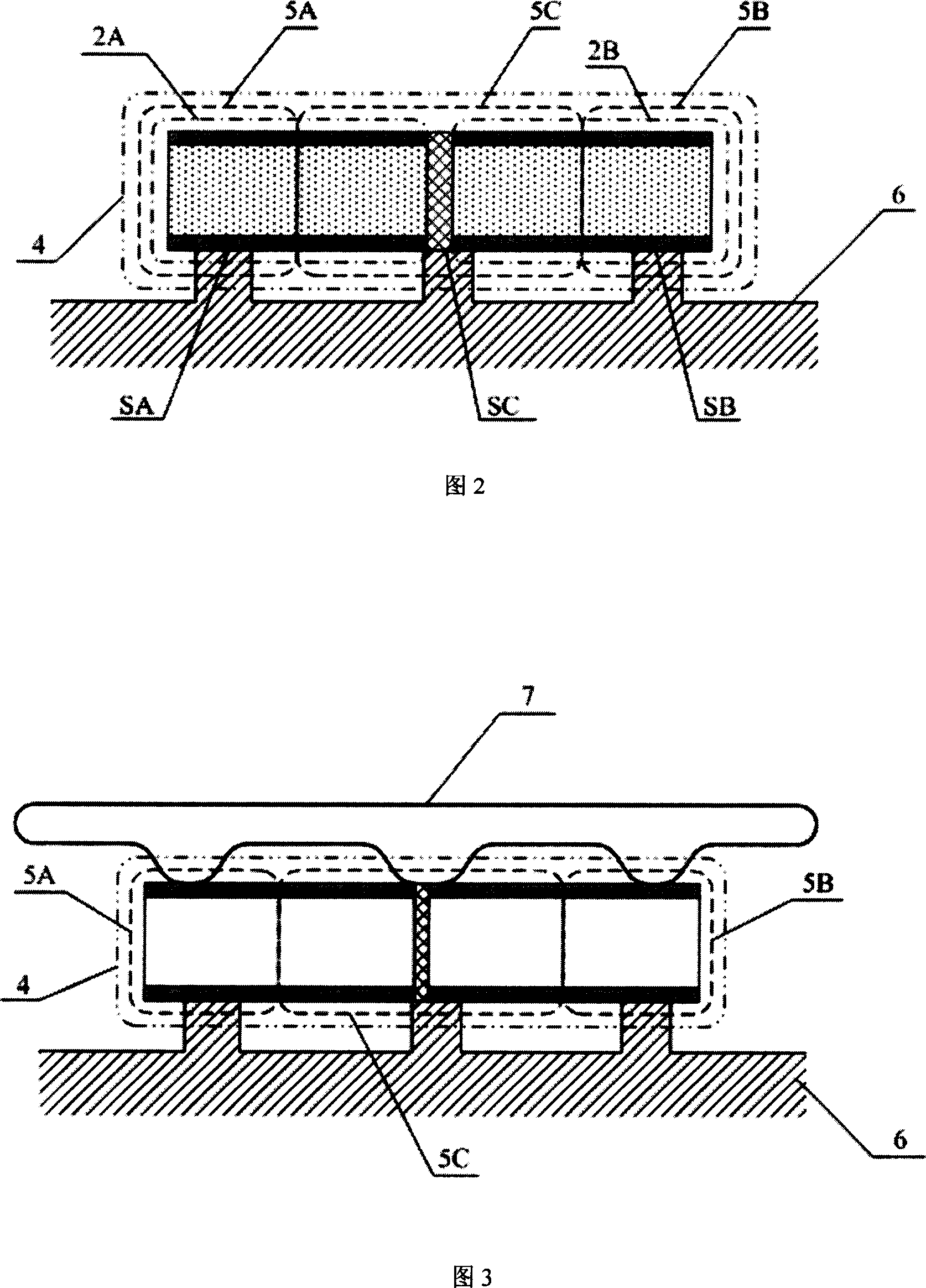
[0088] If the gravity of the dijoint itself is used as its pressure on the base body to generate friction and then generate driving force, this driving force is often relatively small and cannot meet many practical needs, especially when it is required to drive in the vertical direction. In this embodiment, by adding a force applying body, the left area, the middle area and / or the right area of ​​the dijoined body are pressed against the substrate with the force applying body, which makes the dijoined body generate greater pressure on the base body to produce more Greater friction, and thus greater thrust.

[0089] As shown in Fig. 3, the two conjoined body 4 is placed on the base body 6 and acts on the left area, the middle area and / or the right area of ​​the two conjoined body 4 with a force applying body 7, and the force applying body 7 uses elasticity, gravity and / or Or the electromagnetic force presses the dyad 4 onto the sub...

Embodiment 3

[0090] Embodiment 3: Forced Pad Driver

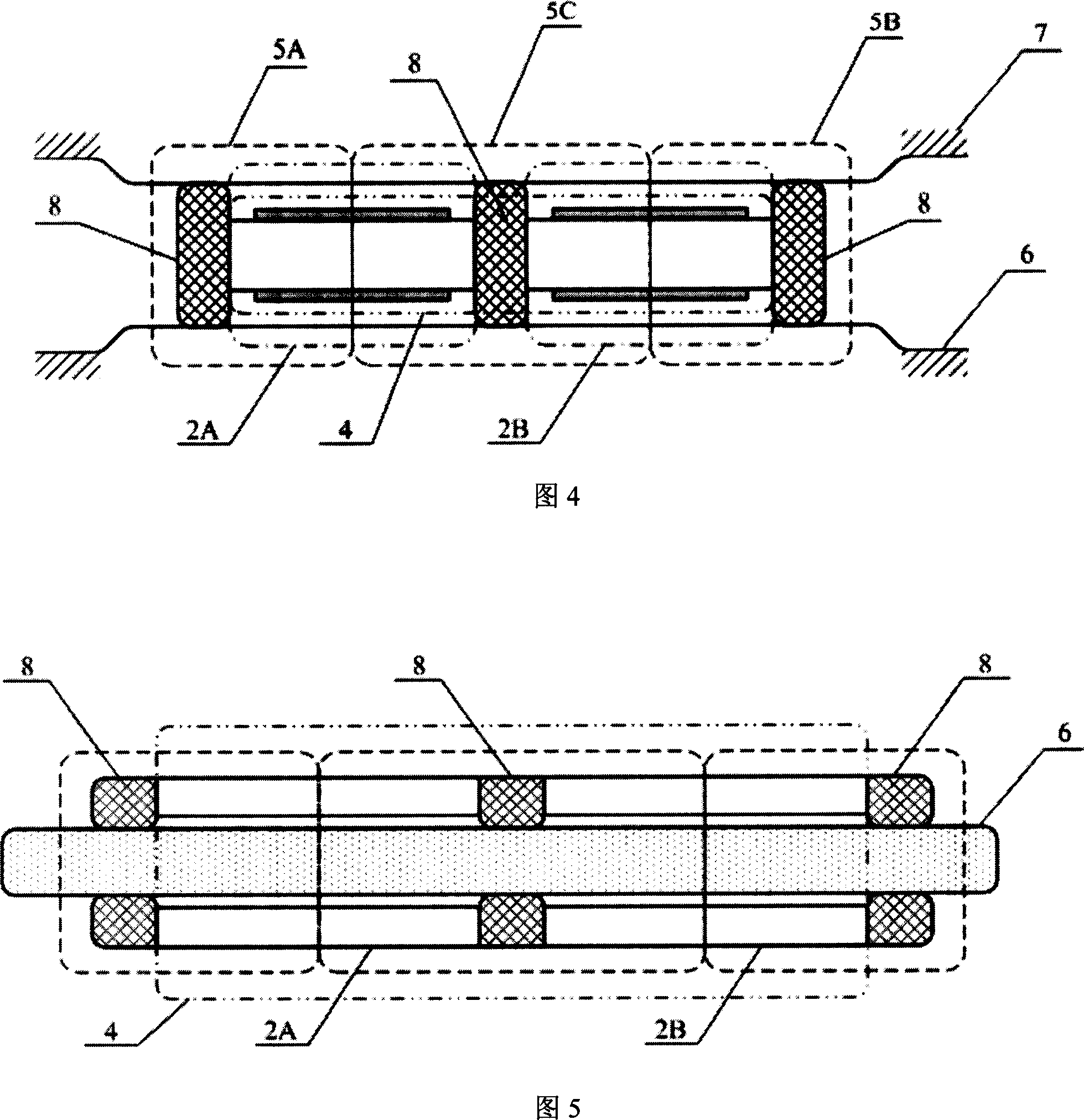
[0091] As shown in Figure 4, the present embodiment is on the basis of the above-mentioned embodiment on the left area 5A, the middle area 5C and / or the right area 5B of the two conjoined body 4, and the force-bearing pad 8 is fixed with the base body 6 with the force-bearing pad 8. The effect of pressure is to protect the two conjoined body 4 or the base body 6, change the pressure between each zone and the base body 6, change the acting area of ​​the pressure, and change the coefficient of static friction. In a word, the maximum friction between the two conjoined body 4 and the base body 6 can be adjusted static friction. The pressure between the force pad 8 and the base body 6 comes from the original pressure of the area where it is located and the base body, and also can come from its own force on the base body, including its gravity, electromagnetic force, elastic clamping force, and can also come from external force. The pressure...


PUM


Abstract

This invention relates to one double voltage line nanometer piezoelectricity driver, its control method and controller, which is characterized by the following parts: left and right piezoelectricity drivers are connected by mechanic series to form two connectors independently and controllable with middle, left and right areas; the base sliding along shape direction matching with two connector is set vertical to the connectors and the three areas separately form friction force.

Description

technical field [0001] The invention relates to a piezoelectric motor, more specifically a piezoelectric actuator composed of a piezoelectric body and a control electrode arranged on the piezoelectric body, and a control signal provided by a controller to enable the piezoelectric actuator to realize nano-positioning piezoelectric motor. Background technique [0002] There are many types of existing piezoelectric motors, but none of them can have most of the important advantages provided by piezoelectric materials at the same time, including: low price, firm structure, small size, easy integration, large stroke, Two-way controllable propulsion, nanometer precision, strong thrust, large working temperature range, and can work in extreme physical environments such as ultra-low temperature, ultra-high vacuum and ultra-strong magnetic field. A key reason for the lack of all-round piezoelectric motors is that these requirements conflict with each other in many places. It is easy...

Claims


Application Information

Patent Timeline
Patent Type & Authority Applications(China)
IPC IPC(8): H02N2/00H02N2/02H02N2/06H01L41/08H01L41/09
Inventor 陆轻铀侯玉斌
Owner UNIV OF SCI & TECH OF CHINA
Why Eureka
Try Eureka