A method and system for traffic control

A data volume and receiving buffer technology, which is applied in transmission systems, digital transmission systems, electrical components, etc., can solve the problems of reducing the bandwidth utilization efficiency of the Iub interface, increasing the data transmission of the Iub interface, and reducing the timeliness of flow control, etc., to achieve effective Utilization, ensure priority transmission, and improve the effect of utilization

Inactive Publication Date: 2007-07-11
HUAWEI TECH CO LTD
View PDF0 Cites 9 Cited by
  • Summary
  • Abstract
  • Description
  • Claims
  • Application Information

AI Technical Summary

Problems solved by technology

[0010] (1) During the flow control process, the RNC sends a capacity request to the NodeB, and the NodeB returns to the RNC after retrograde capacity allocation according to the capacity request, and a certain delay will be generated when the capacity request control frame and the capacity allocation control frame are transmitted on the Iub interface , therefore, the response speed of flow control is slow, which reduces the timeliness of flow control
[0011] (2) The capacity request control frame and the capacity allocation control frame increase the data transmission on the Iub interface while carrying out flow control, and reduce the bandwidth utilization efficiency of the Iub interface
[0012] (3) Although NodeB considers the transmission bandwidth of the Iub interface when carrying out capacity allocation, NodeB carries out capacity allocation based on the average transmission bandwidth within a certain period of time, and although RNC performs data transmission according to capacity allocation information, its data transmission Have suddenness and randomness, therefore, at a certain moment, the amount of data sent by RNC will exceed the transmission bandwidth of the Iub interface, thereby generating data conflicts on the Iub interface; at a certain moment, the amount of data sent by RNC is relatively small, so that it cannot fully Using the Iub interface to transmit bandwidth

Method used


Image

  • A method and system for traffic control
  • A method and system for traffic control
  • A method and system for traffic control

Examples


Embodiment Construction

[0039] In order to make the object, technical solution and advantages of the present invention clearer, specific examples are given below to further describe the present invention in detail.
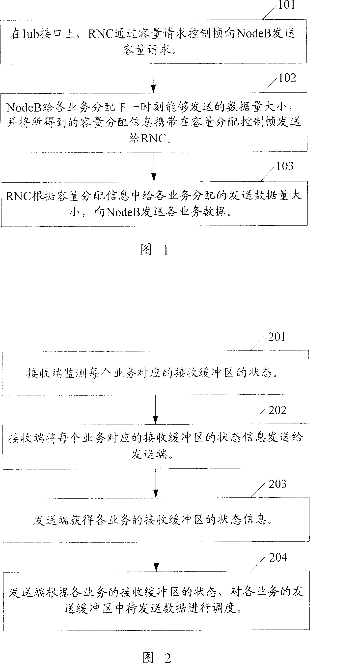
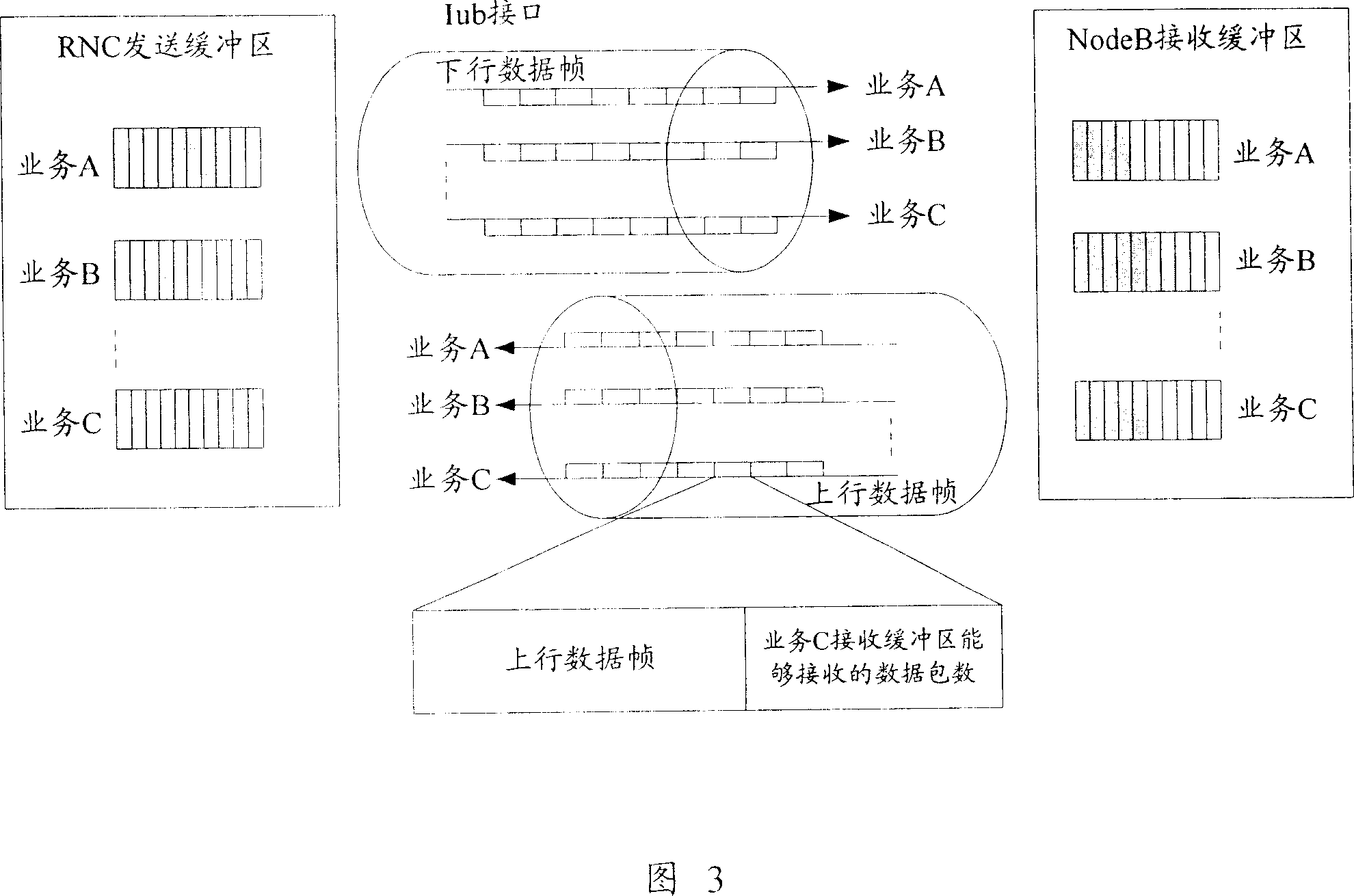
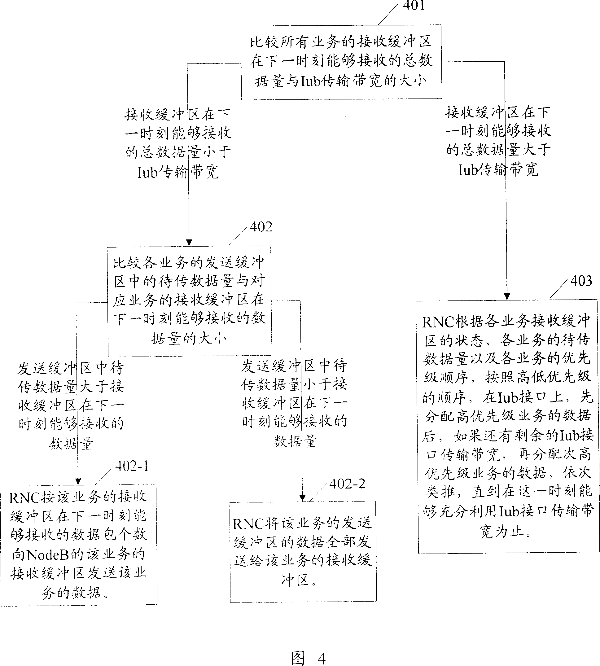
[0040] The overall idea of ​​the present invention to realize flow control is: the receiving end monitors the state of the receiving buffer in real time, and carries the state information of the receiving buffer in the reverse data frame sent to the sending end; the sending end according to the state information of the receiving buffer, Schedule the data to be sent. In the present invention, flow control is implemented between the sending end and the receiving end based on the buffer state of the receiving end. This flow control method can not only improve the timeliness of flow control, but also fully utilize the transmission bandwidth of the interface between the sending end and the receiving end, and can reduce data conflicts on the interface between the sending end and the receiving ...


PUM


Abstract

This invention discloses one method to control flow between send and receive ends, which comprises the following steps: receive end monitors and receives buffer status and takes buffer status information in the reverse data frame and sends it to the send end; send end transfers the data according to the status information. This invention also discloses one system for flow control, which comprises send buffer area, transfer unit and reverse data input unit.

Description

technical field [0001] The invention relates to flow control technology, in particular to a method and system for realizing flow control between a sending end and a receiving end. Background technique [0002] In a communication system, in order for the data sent by the sender to be received by the receiver in time, it is necessary to control the rate at which the sender sends data in time, that is, flow control between the sender and the receiver is required. Through flow control, the transmission delay of data between the sending end and the receiving end can be reduced, and data congestion on the interface between the sending end and the receiving end can be avoided, resulting in partial data loss; at the same time, the receiving buffer at the receiving end is still Under the premise of being able to receive data, let the data in the sending buffer of the sending end be transmitted to the receiving end as soon as possible. [0003] High Speed ​​Downlink Packet Access (HS...

Claims


Application Information

Patent Timeline
Patent Type & Authority Applications(China)
IPC IPC(8): H04L12/56H04L12/26H04L12/861
Inventor 张静荣
Owner HUAWEI TECH CO LTD
Why Eureka
Try Eureka