Method for detachable poster hanging and magnetic poster holder device

a magnetic and poster holder technology, applied in the direction of display means, show hangers, show cards, etc., can solve the problems of inability to shorten the profile without further ado, the magnetic clip is typically not suitable for hanging, and the profile becomes less flexible, so as to achieve sufficient fixing

Active Publication Date: 2018-06-19
MAGSEE
View PDF21 Cites 1 Cited by
  • Summary
  • Abstract
  • Description
  • Claims
  • Application Information

AI Technical Summary

Benefits of technology

[0009]Furthermore, the invention relates to a magnetic poster holder unit with a hanging profile where a magnet clip is u- or v-shaped and in the bottom, where the v-shape's legs meet, is provided with a magnet and where the magnet clip in the top, where the v-shape's legs end, on the external side is designed with notches, whereby the magnet clip can be clicked into the hanging profile, which has an inner shape, which corresponds to the outer shape of the magnet clip such that the magnet clip's notch by insertion in the hanging profile can provide a mechanical locking and thereby fixation between the magnet clip and the hanging profile.
[0010]By this poster holder unit is achieved possibility of simple assembly and / or disassembly of a hanging profile and magnet clips such that magnet clips with magnetic items can easily and unhindered be inserted and mechanically fixed in the hanging profile. The corresponding inner shapes of the hanging profile and the outer shape of the magnet clips ensure a mechanical locking such that the magnet clips do not become released from the poster holder unit without the user's intention. On the other side, the choice of a profile for hanging and magnet clips for fitting in it contributes to making it relatively easy to displace magnet clips in place in the hanging profile in its longitudinal direction.
[0011]In an embodiment, the hanging profile consists of an extruded profile in light metal or polymeric material or the profile is designed in wood. The fact that the hanging profile is relatively easy to manufacture as a profile in metal, plastic or wood makes it possible to have profitable production in both large and small series. Also, the 3 materials give the user possibility of shortening profiles, as needed and desired, himself.
[0012]In an embodiment of the invention, the hanging profile includes items for fixing towards wall, ceiling or to a rack. The profile can have all three options built in or just one of them. A possible realization of this is that the hanging profile includes an open C profile provided in connection to the u- or v-profile for fixing of the magnet clips. In such a C-profile, it will be easy to mount different forms of binding agents, brackets or hanging rings, which make wall-, ceiling- or rack mounting simple and straightforward for the user to carry out.
[0013]In yet another embodiment, the magnet clip is shorter than the hanging profile such that a number of magnet clips are mountable after each other in the hanging profile's longitudinal direction. Hereby, the user can easily vary the magnetic force by inserting more or less magnet clips in the hanging profile.
[0016]In an embodiment, the distance between the steps on the hanging profile's u-profile and the distance between external notches in the magnet clips are matching, such that the notches will go in mesh with the steps when the magnet clips are inserted into the hanging profile's u-profile. The correspondence between the distances does not need to be absolute, since there can be accepted a little play. Even with a little play, the fixing will be sufficiently good and if there should be a certain oversize in the distance between the notches on the individual magnet clip, one can also, as a result of the parts' springy characteristics, get the systems to function well anyhow.

Problems solved by technology

Methods of this type have the weakness that the magnet clip is typically not suited for hanging.
There is known a system for magnetic suspension, in which the magnets are fixed connected to a suspension profile but hereby this profile becomes less flexible and furthermore, the end user cannot without further ado shorten the profile as needed since the fixed built in magnets also have to be sawed through.

Method used


Image

  • Method for detachable poster hanging and magnetic poster holder device
  • Method for detachable poster hanging and magnetic poster holder device
  • Method for detachable poster hanging and magnetic poster holder device

Examples


Embodiment Construction

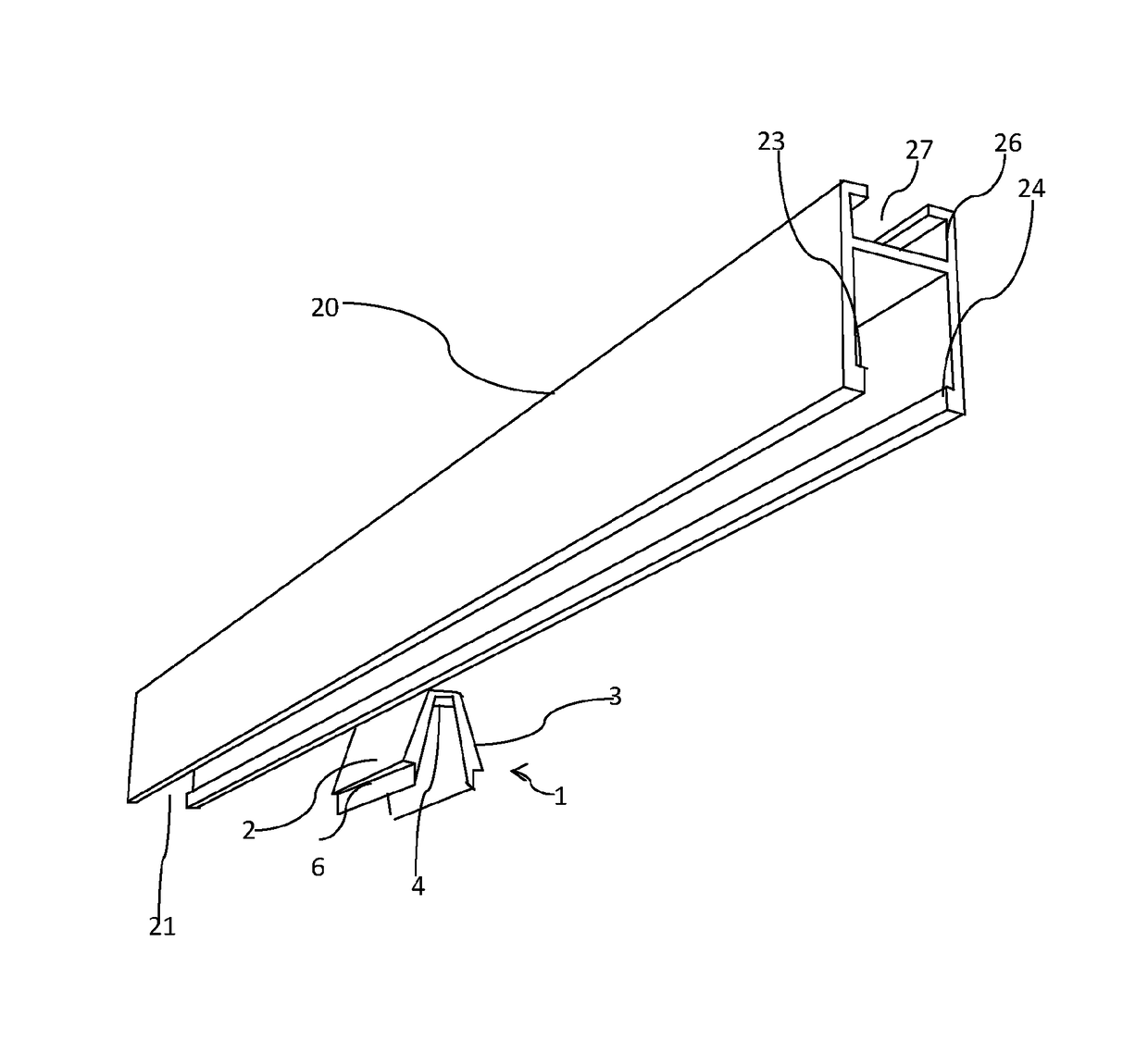
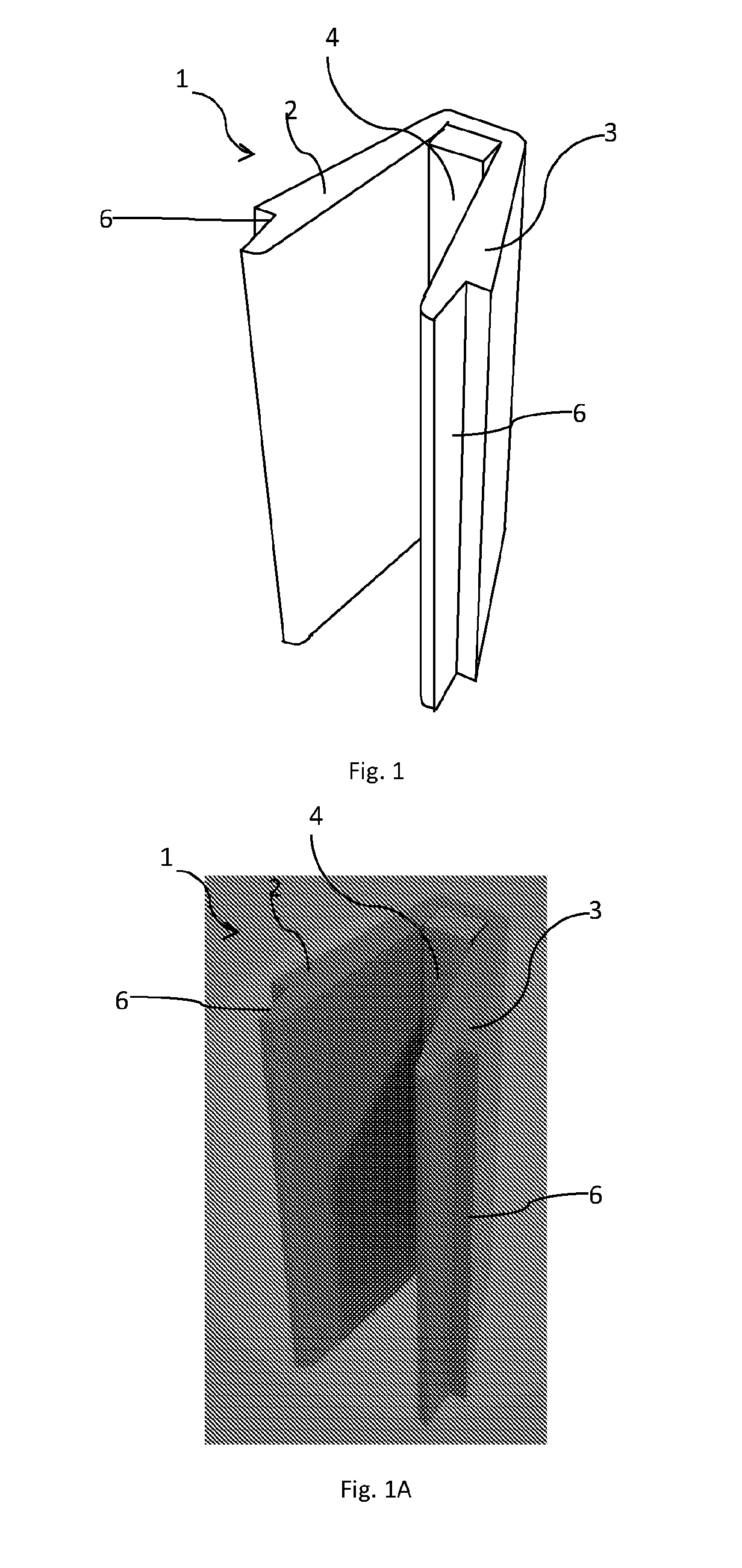
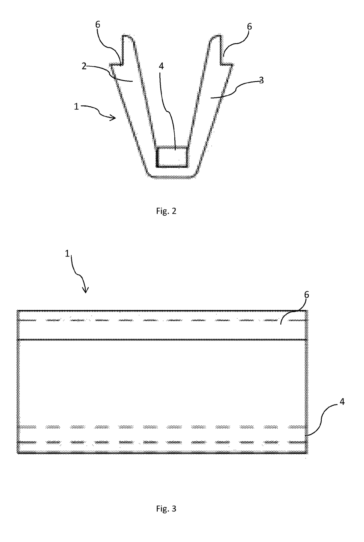
[0033]In FIG. 1 is seen a v-shaped item consisting of a magnet clip 1, with magnetic items 4 placed between a first leg 2 and another leg 3 of the magnet clip's v-shaped profile. When a poster edge with corresponding magnetic items is inserted between the two legs 2,3 for contact against the magnetic items 4, the pull between the two sets of magnetic items will cause a detachable fixing of the poster edge in the bottom of the magnet clip. Hereby, a poster edge can detachably be hanged along its edge. The magnetic items can actually be polarized permanent magnets mounted in the magnet clip, which are counterbalanced by opposite polarized magnets along a poster edge, or there can be a case of combinations of magnetizable iron and permanent magnets. In the magnet clip, the magnetic items can be embedded, glued on or fixed in other ways, for example by a click connection or screw connection. The poster will typically be shaped by flat, flexible length material, for example woven or felt...


PUM


Abstract

The invention relates to a magnetic poster holder unit, where a v- or u-shaped magnet clip in the bottom is provided with a magnet. According to the invention, the magnet clip is in the top, on the outer side, designed with notches, whereby the magnet clip can be clicked into a hanging profile, which has an inner shape, which corresponds to the outer shape of the magnet clip, such that the magnet clip's notch by insertion in the hanging profile can provide a mechanical locking and thereby fixation between the magnet clip and the hanging profile. The invention also relates to a method for detachable hanging of poster of flat, flexible length material along a poster edge, where the poster edge includes magnetic items and where the poster edge's magnetic items are brought to contact against a magnet clip containing corresponding magnetic items.

Description

CROSS-REFERENCE TO RELATED APPLICATIONS[0001]This application is a U.S. national stage of International Appl. No. PCT / DK2015 / 050256 filed 1 Sep. 2015, which claimed priority to Danish Appl. Nos. PA 2014 00538 filed 22 Sep. 2014 and PA 2014 70627 filed 10 Oct. 2014, which applications are all incorporated herein by reference in their entireties.TECHNICAL FIELD[0002]The invention relates to a method for detachable poster hanging of flat, flexible length material along a poster edge. The poster edge has magnetic items and the poster edge's magnetic items are brought to contact against a magnet clip containing corresponding magnetic items for detachable magnetic fixing of the poster edge against the magnet clip.BACKGROUND[0003]From DE 202009000282U1 is known a suspension device for posters, where the device includes a rail with a magnet designed to co-operate with a wire in the poster's edge.[0004]Methods of this type have the weakness that the magnet clip is typically not suited for ha...

Claims


Application Information

Patent Timeline
Patent Type & Authority Patents(United States)
IPC IPC(8): B42F15/06B44C5/02A47F7/14G09F7/18G09F7/20G09F1/10G09F15/00
CPCB42F15/066A47F7/143B44C5/02G09F1/103G09F7/18G09F7/20G09F15/0018G09F2007/1852G09F2007/1856G09F2007/186
Inventor PEDERSEN, TOMAS
Owner MAGSEE
Why Eureka
Try Eureka