Method for measuring characteristics of a transmitter unit of a device under test, test system and radio frequency device

a transmitter unit and characteristics technology, applied in the direction of transmission, power amplifiers, amplifiers, etc., can solve the problems of repeated signal distortion, memoryless digital pre-distortion is incapable of compensating memory effects that affect the efficiency of digital pre-distortion, and memory mitigation digital pre-distortion is very complex, so as to achieve high fidelity of the signal processed by the transmitter uni

Active Publication Date: 2018-06-19
ROHDE & SCHWARZ GMBH & CO KG
View PDF7 Cites 35 Cited by
  • Summary
  • Abstract
  • Description
  • Claims
  • Application Information

AI Technical Summary

Benefits of technology

[0026]According to a certain embodiment, said baseband processing unit compares said output signal with an expected signal for determining said first and second pre-distortion parameters. The baseband processing unit, in particular its pre-distortion sub-unit, adapts the pre-distortion parameters such that the signal measured by the measuring unit corresponds to an expected signal, for instance the original one with regard to the signal fidelity. If the pre-distortion parameters are well defined, a high fidelity of the signal processed by the transmitter unit will be ensured.
[0027]Particularly, said baseband processing unit divides a composition of said output signal into two parts wherein a first part relates to an increasing input amplitude for said first pre-distortion parameter and a second part relates to a decreasing input amplitude for said second pre-distortion parameter. Thus, the signal output and forwarded to the baseband processing unit is processed such that a population of measured signal points is created which is divided into two parts for an increasing input amplitude and a decreasing input amplitude. Accordingly, the baseband processing unit may determine the pre-distortion parameters appropriately and in an efficient manner.

Problems solved by technology

This signal distortion is expected to occur repetitive while using the radio transmitter unit.
The memoryless digital pre-distortion is incapable of compensating memory effects that affect the efficiency of the digital pre-distortion.
However, memory mitigation digital pre-distortion is very complex such that those systems are not suitable for small radio frequency devices such as a mobile device.
Misalignments in the time of arrival of both signals cause a degraded linearity and increased memory effects wherein these memory effects result in degraded linearity.
However, there is a need for a pre-distortion technology being less complex, but effective.

Method used


Image

  • Method for measuring characteristics of a transmitter unit of a device under test, test system and radio frequency device
  • Method for measuring characteristics of a transmitter unit of a device under test, test system and radio frequency device
  • Method for measuring characteristics of a transmitter unit of a device under test, test system and radio frequency device

Examples


Embodiment Construction

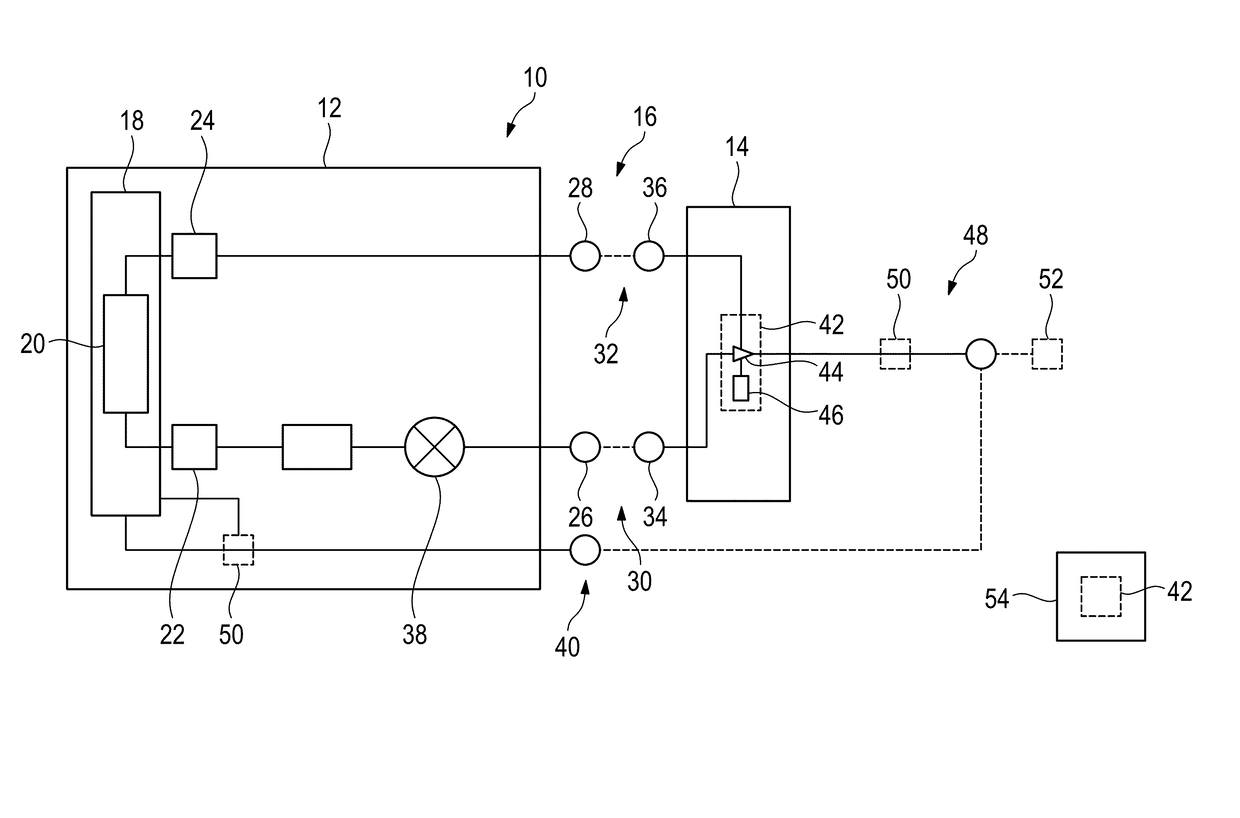
[0048]In FIG. 1, a test system 10 is schematically shown which comprises a signal generator 12 and a device under test 14 wherein the signal generator 12 and the device under test 14 are connected with each other via an interface 16.

[0049]The signal generator 12 comprises a baseband processing unit 18 having at least a digital pre-distortion sub-unit 20 that is connected to a first signal generator unit 22 and a second signal generator unit 24. Both signal generator units 22, 24 are each assigned to a corresponding output 26, 28 wherein the first output 26 is part of a radio frequency forward interface 30 whereas the second output 28 is part of the backward interface 32.

[0050]The radio frequency forward interface 30 and the backward interface 32 define the interface 16. Accordingly, the device under test 14 has two inputs 34, 36 which are connected with the outputs 26, 28 via the radio frequency forward interface 30 and the backward interface 32, respectively.

[0051]Particularly, the...


PUM


Abstract

A method for measuring characteristics of a transmitter unit of a device under test is described. A signal generator is provided that comprises a baseband processing unit having at least a digital pre-distortion sub-unit. A device under test is provided that has a transmitter unit. A measuring unit is provided. Said signal generator and said device under test are connected with each other via an interface. At least one input signal is generated by using said signal generator, said input signal is forwarded to said device under test. An output signal of said device under test is measured by using said measuring unit. A first pre-distortion parameter for an increasing input amplitude is determined by using said digital pre-distortion sub-unit. A second pre-distortion parameter for a decreasing input amplitude is determined by using said digital pre-distortion sub-unit. Said first and second pre-distortion parameters are determined such that said output signal has a high fidelity. Further, a test system and a radio frequency device are described.

Description

TECHNICAL FIELD[0001]The invention relates to a method for measuring characteristics of a transmitter unit of a device under test, a test system as well as a radio frequency device.BACKGROUND OF THE INVENTION[0002]In many applications for radio transmitters it is desirable to minimize power consumption whilst achieving sufficient signal fidelity or linearity. For instance, the power consumption is minimized by using an envelope tracking (ET) technique of the power supply whereas the desired signal fidelity or linearity is achieved by using digital pre-distortion (DPD) technique. Hence, digital pre-distortion techniques are typically used in radio frequency applications, in particular in radio transmitters.[0003]By using the digital pre-distortion technique, a signal distortion is determined that is caused by a transmitter unit of the radio frequency device that processes the signal, in particular by a unit of the transmitter unit that has an amplifying function. This signal distorti...

Claims


Application Information

Patent Timeline
Patent Type & Authority Patents(United States)
IPC IPC(8): H04B1/04H04B17/15
CPCH04B17/15H04B1/0475H04B17/13H03F1/32H03F3/24H04B1/04H04B17/0085H04B2001/0425G06F30/36H03F1/3241
Inventor LLOYD, PAUL GARETH
Owner ROHDE & SCHWARZ GMBH & CO KG
Why Eureka
Try Eureka