
High fidelity feedthrough system

a feedthrough system and high-fidelity technology, applied in the direction of insulators, basic electric elements, electric devices, etc., can solve the problems of poor conductivity of steel required for this system, sacrifice electrical performance for mechanical functionality, and low thermal expansion rate of aforementioned terminals, so as to enhance power transmission economy, increase electrical performance and reliability, and prolong the service life of electro-mechanical devices

Active Publication Date: 2020-11-24
BELLORA ANTHONY
View PDF8 Cites 0 Cited by
  • Summary
  • Abstract
  • Description
  • Claims
  • Application Information

AI Technical Summary

Benefits of technology

[0009]The object of the present invention is to significantly increase electrical performance and reliability of airborne electro-mechanical devices over present seals.
[0010]Another object is to enhance power transmission economy through the use of highly conductive materials.Another object is to enhance signal fidelity by use of nonmagnetic conductors.
[0011]Yet another object is to extend service life of electro-mechanical devices by reduction of thermal incompatibility between avionics packages and present technology feedthrough seals.
[0012]A further object is to design the highly efficient & reliable feedthrough system with commercially available materials to provide reasonable cost and availability.

Problems solved by technology

Though these materials will provide a hermetic glass to metal seal over a wide temperature range they sacrifice electrical performance for mechanical functionality.
The steel required for this system is a poor conductor of electricity and exhibits magnetic properties.
As magnetic steel is a poor choice for electrical conduction, designers must accept a certain power loss tax and signal noise when hermetic circuit packages are required.
The secondary undesirable attribute is the low thermal expansion rate of the aforementioned terminal.
The pliability of solder is not sufficient to absorb these stresses inducing microcracks with every temperature swing.
These cracks grow over continual temperature cycling leading to joint fatigue and eventual seal failure.
These feedthrough solder joints fail first under extensive low cycle fatigue, representing the service life limit for hermetic avionics.

Method used


Image

  • High fidelity feedthrough system
  • High fidelity feedthrough system
  • High fidelity feedthrough system

Examples


Embodiment Construction

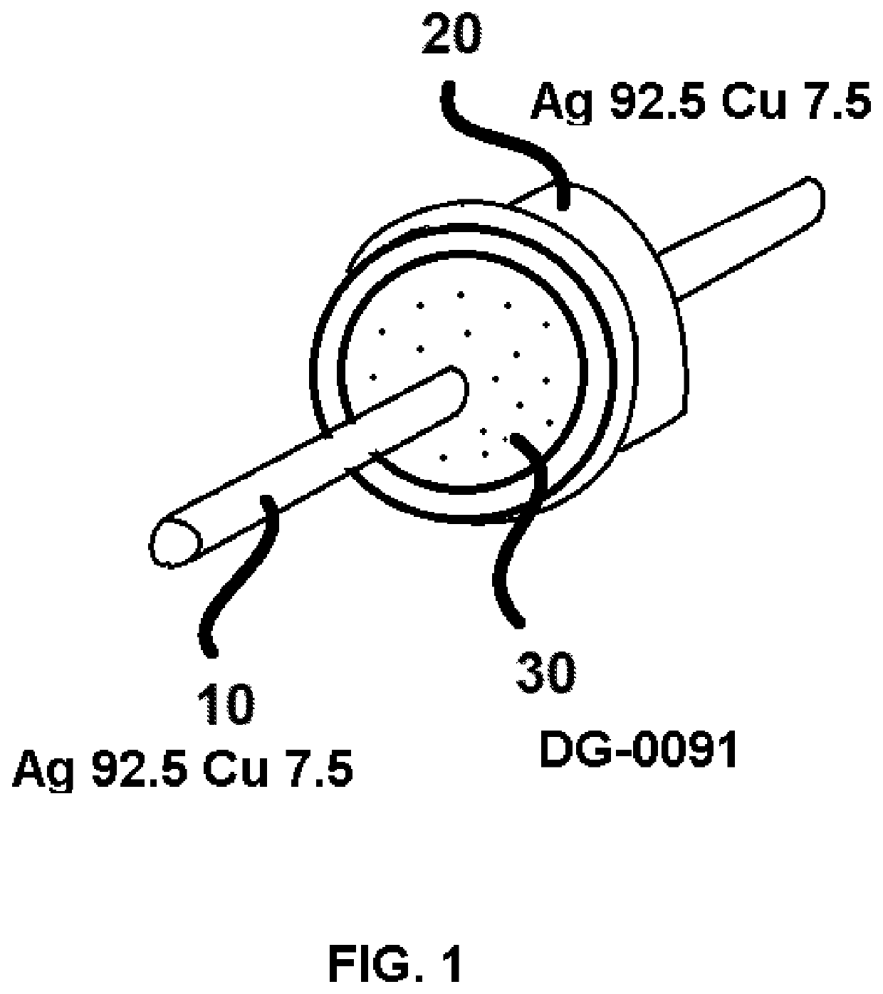
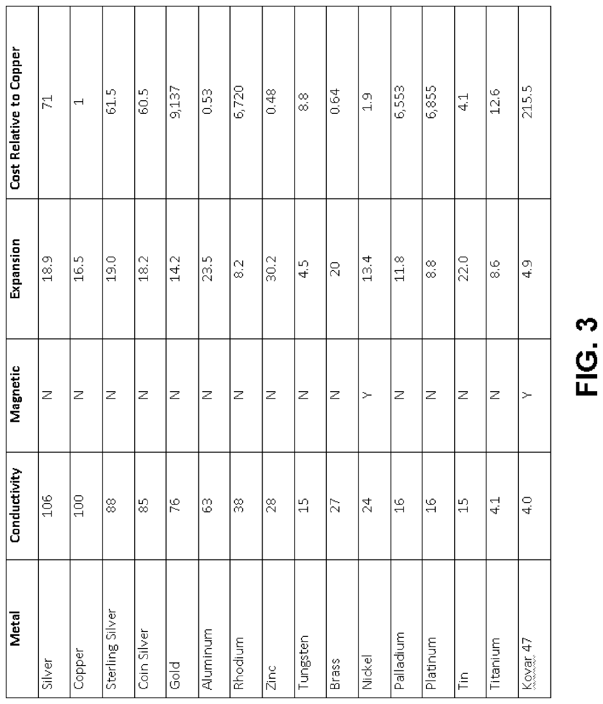
[0021]The present invention is a system of thermal matching components for the construction of hermetic feedthroughs requiring high signal fidelity. The final assembly shall be interchangeable with present terminals for electromechanical device manufacturers. The starting point will be terminal pin and body that are ideal for radio signal transmission. Of primary consideration is conductivity of the pin. The best conductors of electricity are silver and copper. Any alloy combination of these two elements will have high conductivity and no magnetic properties. The secondary property will be the metal stiffness. The barrel must be stiff enough to endure fabrication & the pin must also be tolerant of package handling.

Materials

[0022]In construction of high performance feedthroughs, the primary property of the terminal should be high conductivity. Metals that can be magnetized should be excluded due to their adverse effects on signal integrity. Additionally, resistance to corrosion is ne...


PUM

PropertyMeasurementUnit
dielectric constantaaaaaaaaaa
temperaturesaaaaaaaaaa

Abstract

A system for the manufacturing of high-fidelity insulated components is described. Per field requirements, components crafted via the process are hermetically sealed, and are configured to employ appropriately matched materials in accordance with their inherent properties of thermal expansion. A pin, glass insulator, and ferule are present. As opposed to conventional insulated components which employ stainless steel as an inefficient conductor, the unique matching process of the system provides for the use of copper and silver alloys to maximize efficiency while maintaining a hermetic seal. Specific glass is selected in accordance with the desired alloy in order to maintain similar degrees of expansion and contraction per temperature variations.

Description

FIELD OF THE PRESENT INVENTION[0001]The present invention relates to ideal material matching systems, and more specifically relates to a system for matching insulating materials to appropriate conductive elements for high electrical efficiency and hermetic glass to metal seal. The system shall be designed for high power radio applications to eliminate the generation of heat & Passive Intermodulation Products.BACKGROUND OF THE PRESENT INVENTION[0002]Many types of micro electro-mechanical devices are enclosed in electrically conductive packages that shield delicate construction from the environment. Conductive housing packages are used because they provide a shield from background radiation emissions and sturdy protection from damage. The affordable material of choice for package housing construction is light-weight aluminum, particularly in avionics. The devices inside of the aforementioned sealed package must receive signals via hermetic terminal ports known as feedthroughs. These t...

Claims


Application Information

Patent Timeline
Patent Type & Authority Patents(United States)
IPC IPC(8): H01B19/00H01B17/30C22C5/08
CPCH01B17/305C22C5/08H01B19/00
Inventor BELLORA, ANTHONY
Owner BELLORA ANTHONY
Learn More