Vehicle front portion structure equipped with pedestrian airbag device

a technology for front portion structures and airbags, which is applied in the direction of pedestrian/occupant safety arrangements, vehicular safety arrangments, tractors, etc., can solve the problems of no longer stable deployment direction of airbags and large deformation of cows, and achieve the effect of improving flexibility in the shape of support members

Active Publication Date: 2018-06-26
TOYOTA JIDOSHA KK
View PDF17 Cites 0 Cited by
  • Summary
  • Abstract
  • Description
  • Claims
  • Application Information

AI Technical Summary

Benefits of technology

[0006]In consideration of the circumstances described above, it is an object of preferred embodiments to provide a vehicle front portion structure equipped with a pedestrian airbag device that, in a structure where the inflator is disposed above the cowl front panel, can effectively control deformation of the cowl at the time of airbag deployment.
[0027]As described above, in the vehicle front portion structure equipped with a pedestrian airbag device of the preferred embodiments, deformation of the cowl at the time of airbag deployment can be effectively controlled in a structure where the inflator is disposed above the cowl front panel.

Problems solved by technology

The cowl front panel has a cantilever structure supported from the vehicle rear side, so at the time of airbag deployment, the reaction force acting on the inflator is applied to the cowl front panel, resulting in the cowl becoming deformed a great extent.
As a result, there is the potential for the deployment direction of the airbag to no longer be stable.

Method used


Image

  • Vehicle front portion structure equipped with pedestrian airbag device
  • Vehicle front portion structure equipped with pedestrian airbag device
  • Vehicle front portion structure equipped with pedestrian airbag device

Examples


first embodiment

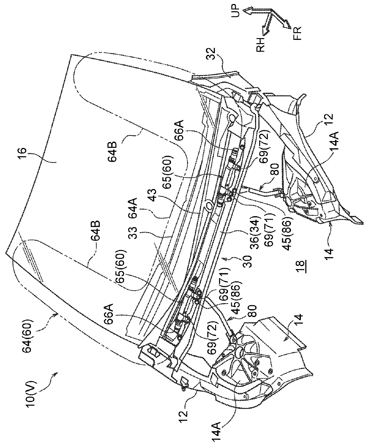
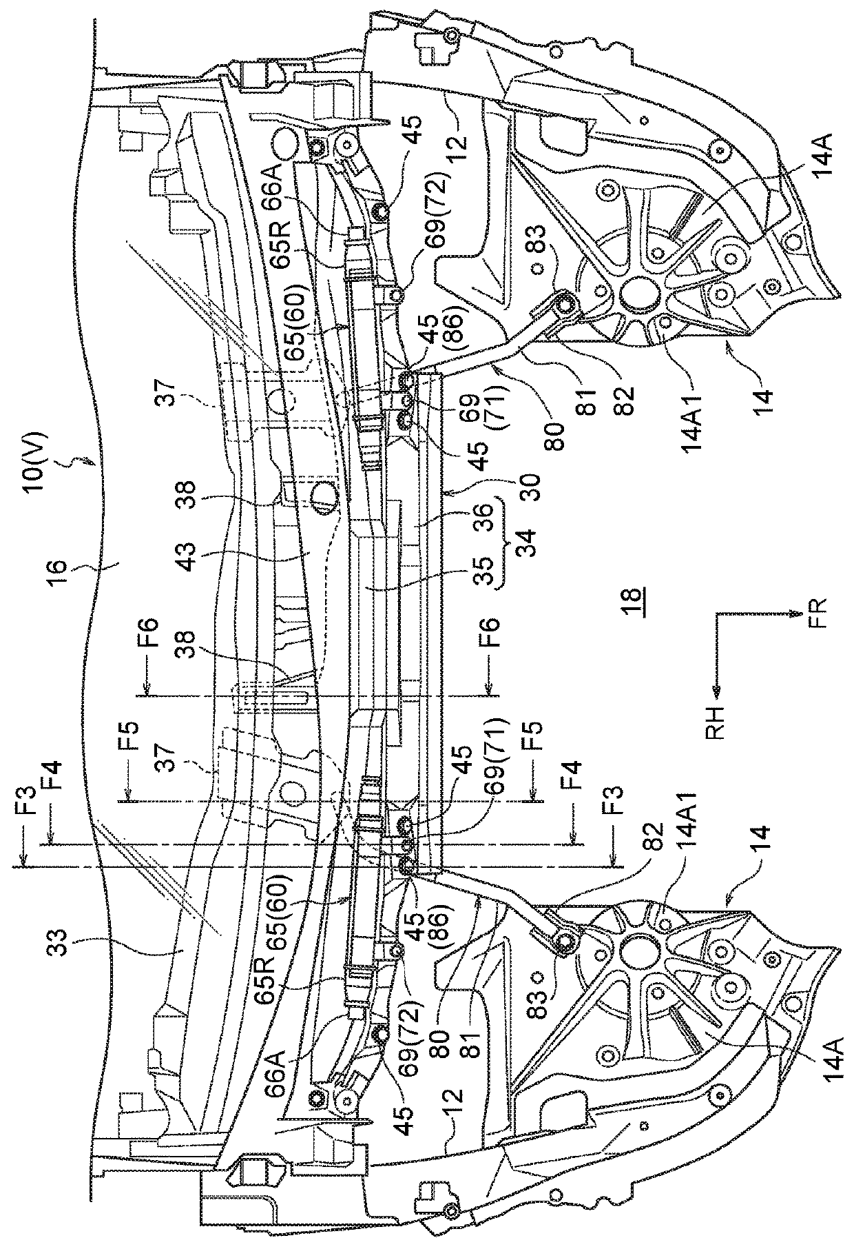
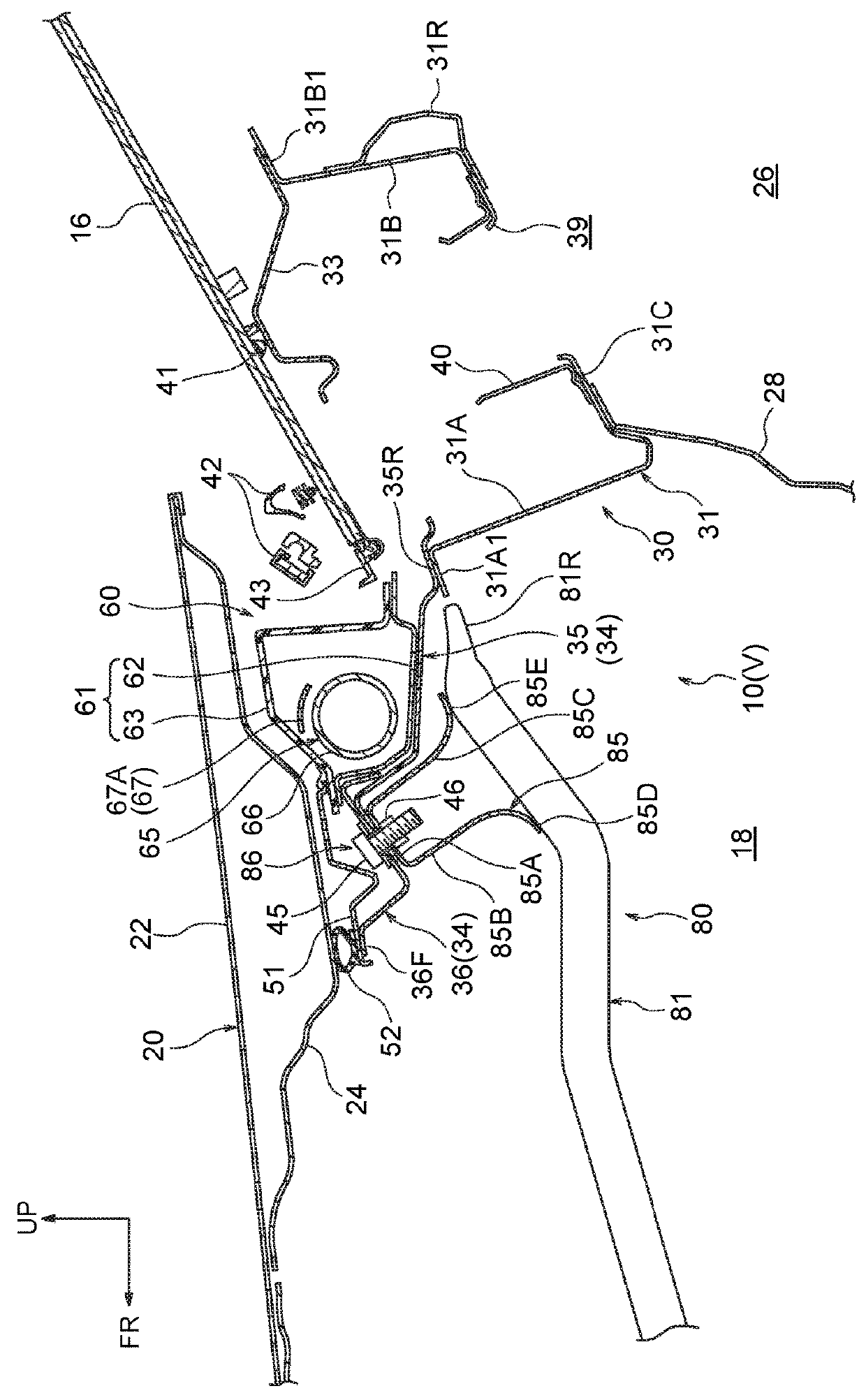
[0045]A vehicle front portion structure 10 equipped with a pedestrian airbag device (hereinafter abbreviated as “the vehicle front portion structure 10”) pertaining to a first embodiment will be described on the basis of FIG. 1 to FIG. 15. It should be noted that there will be cases where the reference signs of some members are omitted from the drawings in order to make it easier to see what is shown in those drawings. Furthermore, arrow FR, arrow UP, and arrow RH appropriately shown in the drawings indicate a forward direction (traveling direction), an upward direction, and a rightward direction of the vehicle, respectively. Hereinafter, when description is given simply using the directions of front / rear, upper / lower, and right / left, unless otherwise specified these will be understood to mean front / rear in the vehicle frontward and rearward direction, upper / lower in the vehicle vertical direction, and right / left in the vehicle rightward and leftward direction (the vehicle width dir...

second embodiment

[0108]In FIG. 16 a vehicle front portion structure 100 equipped with a pedestrian airbag device pertaining to a second embodiment of the present invention is shown by way of a plan view corresponding to FIG. 2. This embodiment differs from the first embodiment in that it has a connection member 102 that links the right and left pair of inflators 65 in the vehicle width direction. The connection member 102 is made of a metal pipe, for example, and is placed with its longitudinal direction coinciding with the vehicle width direction between the right and left inflators 65. Both longitudinal direction end portions of the connection member 102 are secured via brackets (not shown in the drawings) to the vehicle width direction inner end portions of the right and left inflators 65. Because of this, the vehicle width direction inner end portions of the right and left inflators 65 are joined to each other by the connection member 102. It should be noted that the material of the connection m...

third embodiment

[0110]In FIG. 17 a vehicle front portion structure 110 equipped with a pedestrian airbag device pertaining to a third embodiment of the present invention is shown by way of a plan view corresponding to FIG. 2. The airbag module 60 pertaining to this embodiment is equipped with one inflator 112 instead of the right and left pair of inflators 65 pertaining to the first embodiment. The inflator 112 is placed in the vehicle width direction central portion of the cowl front panel 34 and has an inflator body 114 and an attachment bracket 116. The inflator body 114 is a cylinder type inflator like the inflators 65 but it has gas discharge portions 114A in both axial direction end portions and its dimension in the vehicle width direction is set larger than that of each inflator 65.

[0111]The attachment bracket 116 has the same configuration as that of the attachment brackets 67 pertaining to the first embodiment, but its dimension in the vehicle width direction is set larger than that of the...


PUM


Abstract

A vehicle front portion structure, equipped with a pedestrian airbag device, comprises: a cowl comprising a cowl panel and a cowl front panel extending in a forward direction from a front end portion of the cowl panel; an inflator disposed with a longitudinal direction of the inflator coinciding with a vehicle width direction and secured to the cowl front panel; an airbag disposed above the cowl front panel and deployed obliquely in a vehicle rearward and upward direction and outwardly in the vehicle width direction by gas from the inflator; and a support member having one end portion secured to a front suspension tower, extending toward the cowl, and secured to the cowl front panel on a vehicle front side relative to a rear end of the inflator in the vehicle frontward and rearward direction.

Description

CROSS-REFERENCE TO RELATED APPLICATION[0001]This application claims priority under 35 USC 119 from Japanese Patent Application No. 2016-91033, filed on Apr. 28, 2016, the disclosure of which is incorporated by reference herein in its entirety.BACKGROUNDTechnical Field[0002]Preferred embodiments relate to a vehicle front portion structure equipped with a pedestrian airbag device.Related Art[0003]Japanese Patent Application Publication (JP-A) No. 2003-252139 discloses a pedestrian airbag device where an airbag module having an airbag and an inflator is disposed above a cowl panel configuring a cowl. The airbag module is fastened and secured to a front end portion of the cowl panel using stud bolts of the inflator.SUMMARY[0004]In this connection, in vehicles where a cowl front panel is disposed in the cowl so as to extend in the vehicle frontward direction from the front end portion of the cowl panel, there are cases where the airbag module is disposed above the cowl front panel.[0005]...

Claims


Application Information

Patent Timeline
Patent Type & Authority Patents(United States)
IPC IPC(8): B60K28/10B60R21/36B62D25/08
CPCB62D25/081B60R21/36
Inventor KAMIMURA, SHINYA
Owner TOYOTA JIDOSHA KK
Why Eureka
Try Eureka