
Fuel supply system for turbine engines and methods of assembling same

a technology of fuel supply system and turbine engine, which is applied in the direction of turbine/propulsion fuel valve, machine/engine, lighting and heating apparatus, etc., can solve the problem of increasing the overall cost of the combustion turbine engin

Active Publication Date: 2018-07-03
GE INFRASTRUCTURE TECH INT LLC
View PDF15 Cites 1 Cited by
  • Summary
  • Abstract
  • Description
  • Claims
  • Application Information

AI Technical Summary

Benefits of technology

This approach reduces equipment and maintenance costs while effectively reducing NOx emissions and preventing backflow of combustion gases without the need for additional purge systems, enhancing the efficiency and cost-effectiveness of the turbine engine.

Problems solved by technology

However, for at least some turbine engines that operate with only gaseous fuel, adding a separate atomizing air compressor increases the overall cost of the combustion turbine engine.

Method used


Image

  • Fuel supply system for turbine engines and methods of assembling same
  • Fuel supply system for turbine engines and methods of assembling same
  • Fuel supply system for turbine engines and methods of assembling same

Examples


Embodiment Construction

[0011]Unless otherwise indicated, approximating language, such as “generally,”“substantially,” and “about,” as used herein indicates that the term so modified may apply to only an approximate degree, as would be recognized by one of ordinary skill in the art, rather than to an absolute or perfect degree. Approximating language may be applied to modify any quantitative representation that could permissibly vary without resulting in a change in the basic function to which it is related. Accordingly, a value modified by a term or terms, such as “about,”“approximately,” and “substantially,” is not to be limited to the precise value specified. In at least some instances, the approximating language may correspond to the precision of an instrument for measuring the value. Here and throughout the specification and claims, range limitations may be identified. Such ranges may be combined and / or interchanged, and include all the sub-ranges contained therein unless context or language indicates...


PUM


Abstract

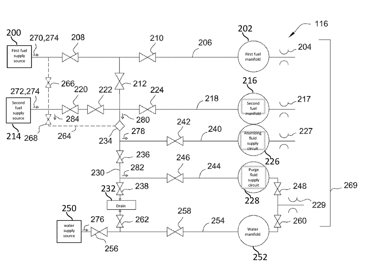
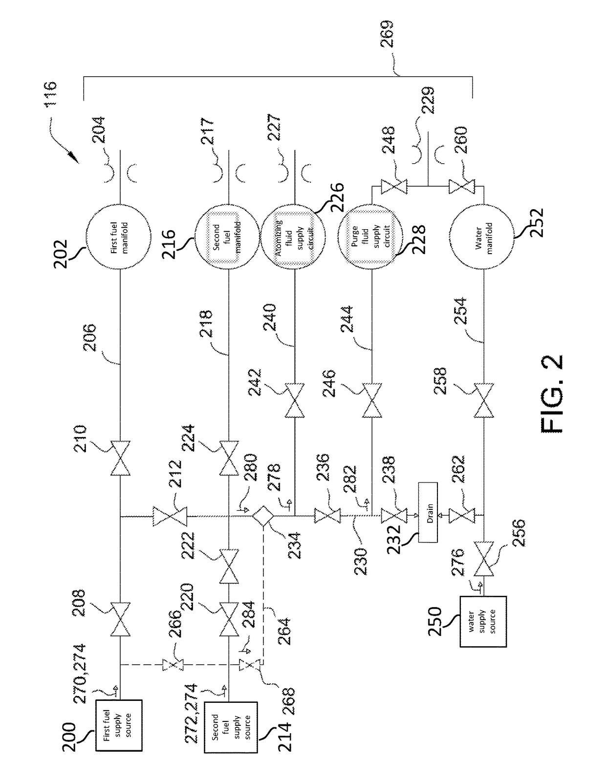
A fuel supply system includes a first fuel supply line coupled in flow communication with a first fuel nozzle and configured to channel a first fuel flow to the first nozzle. A second fuel supply line coupled in flow communication with a second fuel nozzle and configured to channel a second fuel flow to the second nozzle. A water supply line coupled in flow communication with a water injection nozzle and configured to channel a water flow to the water injection nozzle. An atomizing fluid supply circuit coupled in flow communication with the first and second fuel supply lines. The atomizing fluid supply circuit configured to channel an atomizing fluid flow to an atomizing nozzle and into atomizing contact with the water flow. The atomizing fluid includes a portion of at least one of the first fuel flow and the second fuel flow.

Description

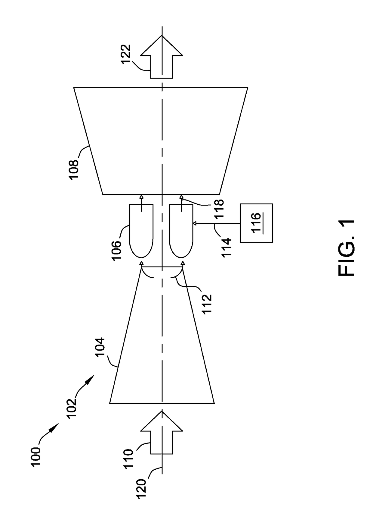
BACKGROUND[0001]The present disclosure relates generally to fuel supply systems and, more specifically, to systems and methods for water atomization in combustor assemblies using combustion turbine engine fuel.[0002]At least some known combustion turbine engines include a compressor, at least one combustor, and a turbine coupled together in a serial flow relationship. More specifically, the compressor and turbine are coupled through a shaft to form a high-pressure rotor assembly. Air entering the turbine engine is mixed with a fuel flow from a fuel supply system and prior to it being ignited in a combustion chamber to form a high energy gas stream. The high energy gas stream flows through the turbine to rotatably drive the turbine such that the shaft rotatably drives the compressor.[0003]The combustion turbine engine may operate with any of several types of fuels including, for example, liquid fuels or gaseous fuels that are supplied to the combustion chamber from the fuel supply sy...

Claims


Application Information

Patent Timeline
Patent Type & Authority Patents(United States)
IPC IPC(8): F23R3/30F23R3/36F02C7/22F02C3/30
CPCF23R3/30F02C7/222F23R3/36F05D2260/212F02C3/305F02C3/30F02C7/22F02C7/232F02C3/22F02C9/40F05D2220/75F23R3/28F23D11/10
Inventor SAHA, RAJARSHITODETI, SUDHAKAR
Owner GE INFRASTRUCTURE TECH INT LLC
Learn More